Feature descriptions, Continued), Vout – GE Industrial Solutions NQR010A0X4 User Manual
Page 15
Data Sheet
March 7, 2012
NQR010A0X4: Non-Isolated DC-DC Power Modules
4.5 – 14Vdc input; 0.59Vdc to 6Vdc Output; 10A output current
LINEAGE
POWER
15
Feature Descriptions
(continued)
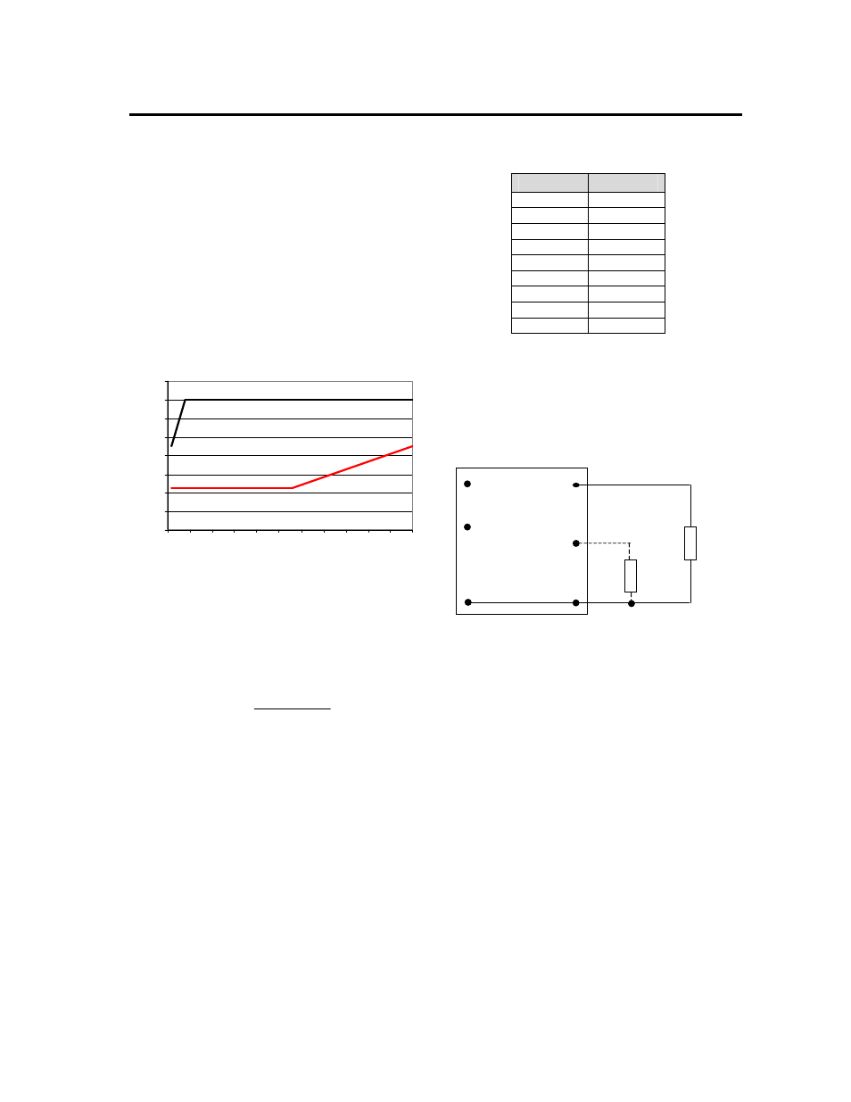
Output Voltage Programming
The output voltage of the NQR010A0X4 10A module
can be programmed to any voltage from 0.59dc to 6Vdc
by connecting a resistor between the Trim+ and GND
pins of the module. Certain restrictions apply on the
output voltage set point depending on the input voltage.
These are shown in the Output Voltage vs. Input
Voltage Set Point Area plot in Fig. 49. The Upper Limit
curve shows that for output voltages of 0.9V and lower,
the input voltage must be lower than the maximum of
14V. The Lower Limit curve shows that for output
voltages of 3.3V and higher, the input voltage needs to
be larger than the minimum of 4.5V.
0
2
4
6
8
10
12
14
16
0.5
1
1.5
2
2.5
3
3.5
4
4.5
5
5.5
6
Output Voltage (V)
Input
V
o
lt
a
g
e (
v
)
Figure 49. Output Voltage vs. Input Voltage Set
Point Area plot showing limits where the output
voltage can be set for different input voltages.
Without an external resistor between Trim+ and GND
pins, the output of the module will be 0.59Vdc. To
calculate the value of the trim resistor, Rtrim for a
desired output voltage, use the following equation:
(
)
Ω
−
=
k
Vo
Rtrim
591
.
0
182
.
1
Rtrim is the external resistor in kΩ
Vo is the desired output voltage
Table 1 provides Rtrim values required for some
common output voltages.
Table 1
V
O, set
(V)
Rtrim (KΩ)
0.59 Open
1.0 2.89
1.2 1.941
1.5 1.3
1.8 0.978
2.5 0.619
3.3 0.436
5.0 0.268
6.0 0.219
By using a ±0.5% tolerance trim resistor with a TC of
±25ppm, a set point tolerance of ±1.5% can be achieved
as specified in the electrical specification. The POL
Programming Tool available at
www.lineagepower.com
under the Design Tools section, helps determine the
required trim resistor needed for a specific output
voltage.
V
O
(+)
TRIM
GND
R
trim
LOAD
V
IN
(+)
ON/OFF
Vout
Figure 50. Circuit configuration for programming
output voltage using an external resistor.
Voltage Margining
Output voltage margining can be implemented in the
NQR010A0X4 10A modules by connecting a resistor,
R
margin-up
, from the Trim pin to the ground pin for
margining-up the output voltage and by connecting a
resistor, R
margin-down
, from the Trim pin to output pin for
margining-down. Figure 51 shows the circuit
configuration for output voltage margining. The POL
Programming Tool, available at
www.lineagepower.com
under the Design Tools section, also calculates the
values of R
margin-up
and R
margin-down
for a specific output
voltage and % margin. Please consult your local
Lineage Power Field Application Engineer or Account
Manager for additional details.