2–1 front panel, 2–2 top panel (test cable connection) – GE Industrial Solutions TVRMS2 Digital Test Kit User Manual
Page 9
TVRMS2 Digital Test Kit
Chapter 2. Controls, Indicators, and Connections
3
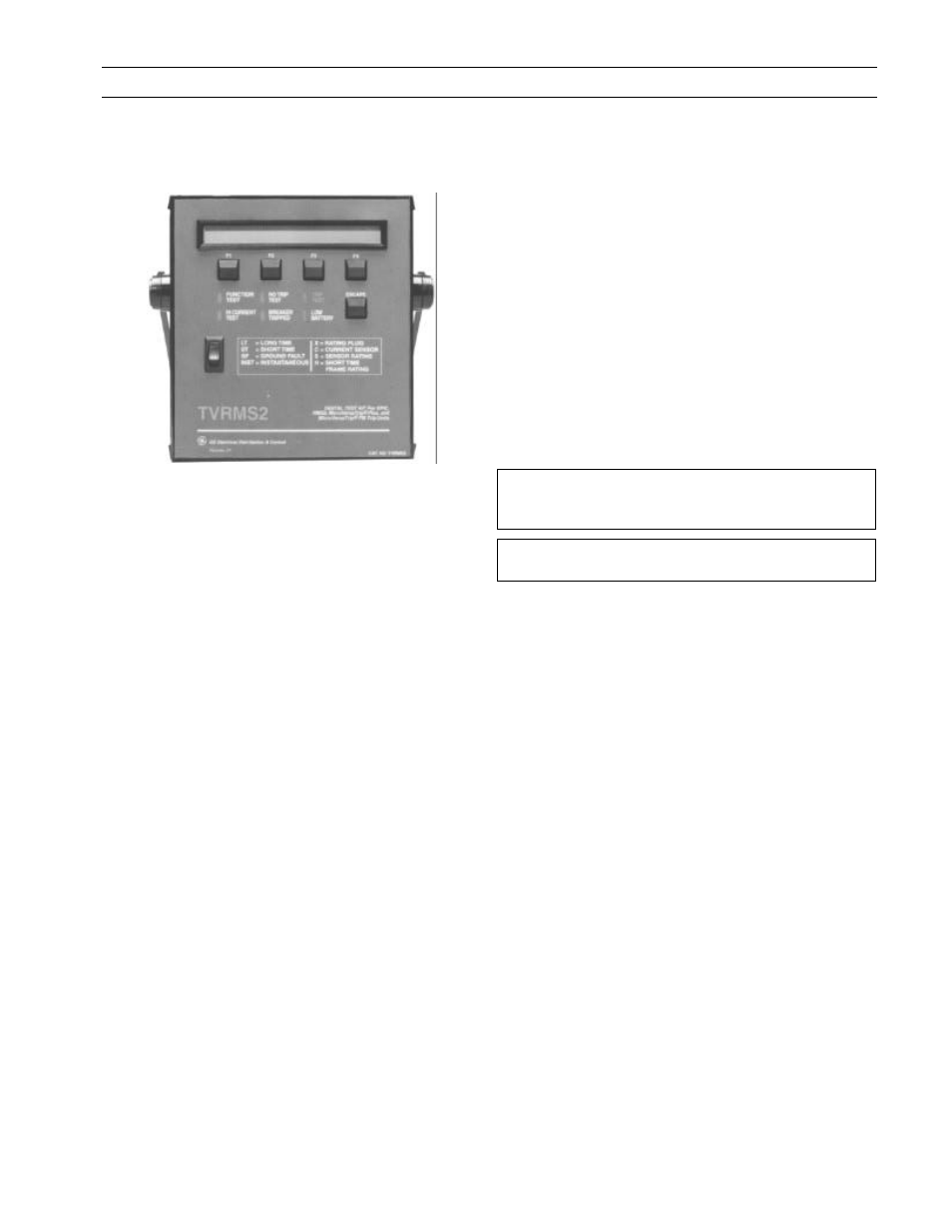
2–1 Front Panel
Figure 2 shows the front panel of the Test Kit.
Figure 2. Front panel of the Test Kit.
The functions of the various switches and displays on the
front panel are as follows:
• Display Panel – The display panel is a 40-character by
2-line liquid crystal display (LCD). The top line
contains instructions and information for each stage
of the test. The bottom line identifies the functions of
each of the four function keys during each test.
• Function Keys – The function of each of the keys is
determined by the test state of the Test Kit and is
identified on the bottom line of the display panel.
The function keys are labeled form left to right as
F1
,
F2
,
F3
, and
F4
.
• LEDs – There are six light-emitting diodes (LEDs) on
the front panel:
FUNCTION TEST
– A yellow LED that lights when
the Test Kit is in the function test sequence.
HI CURRENT TEST
– A yellow LED that lights
when the Test Kit is in the High-Current test
sequence.
NO TRIP TEST
– A yellow LED that lights if the test
being performed will not trip the breaker.
BREAKER TRIPPED
– A red LED that flashes when
the Trip Unit under test has tripped the breaker.
TRIP TEST
– A red LED that flashes if the test
being performed will trip the breaker. This will
occur if
Quick Test
is selected or if
Trip Test
is
selected during an Overcurrent Test sequence.
LOW BATTERY
– A red LED that lights when the
Test Kit battery is becoming weak. Further testing
under low-battery conditions can yield erroneous
test results.
• Escape Key – Pressing the
ESCAPE
key returns the Test
Kit to its power-up or “home” state and initiates the
self-test sequence.
• On-Off Switch – The
ON-OFF
rocker switch has a red
band that is visible when the Test Kit is on.
• Legend – The legend provides a quick reference to the
various abbreviations used on the display.
2–2 Top Panel (Test Cable Connection)
The top panel contains a test port,
Test Port A
, which
accepts the 3.5 mm, three-conductor plug attached to the
test cable. The other end of the test cable is inserted into
the test jack of the Trip Unit rating plug. A similar test
cable can be obtained from Radio Shack (catalog number
42-2387).
CAUTION: Switch the Test Kit power off before inserting
the test jack into or removing it from the Trip Unit rating
plug.
ATTENTION: Eteindre le Test Kit avant de connecter ou
de déconnecter la prise jack du calibreur.