Bus splice kits, Nec work space, Installation of top entry conduits – GE Industrial Solutions Evolution Series E9000 User Manual
Page 10
9
Bus Splice Kits
Table 2. Bus Splice Kits
Splicing From / To E9000/E9000
*Included in kits.
Note: Standard plating is tin. Refer to factory for alternate plating.
NEC Work Space
NEC Work Space is defined in Table 110.26(a) Working
Spaces. Included in these clearance requirements is the
step-back distance from the face of the equipment.
Table 110.26(a) provides requirements for clearances
away from the equipment, based on the circuit voltage
to ground, and whether there are grounded or unground-
ed objects in the step-back space, or if there are exposed
live parts across from each other. The voltages to ground
consist of two groups: 0 to 150 and 151 to 600, inclusive.
Remember, where an ungrounded system is utilized, the
voltage to ground will be the greatest voltage between
the given conductor and any other conductor of the
circuit. For example, the voltage to ground for a 480-
volt ungrounded delta system is 480 volts.
See Figure 14 for general working clearance requirements.
Distances are measured from the live parts if the live
parts are exposed, or from the enclosure front if live
parts are enclosed. If any assemblies, such as switch-
boards or motor control centers, are accessible from the
back and expose live parts, the working clearance
dimensions would be required at the rear of the equipment,
as illustrated. Note that for Condition 3, where there is
an enclosure on opposite sides of the working space,
the clearance for only one working space is required.
Figure 14. General Working Clearance Requirements
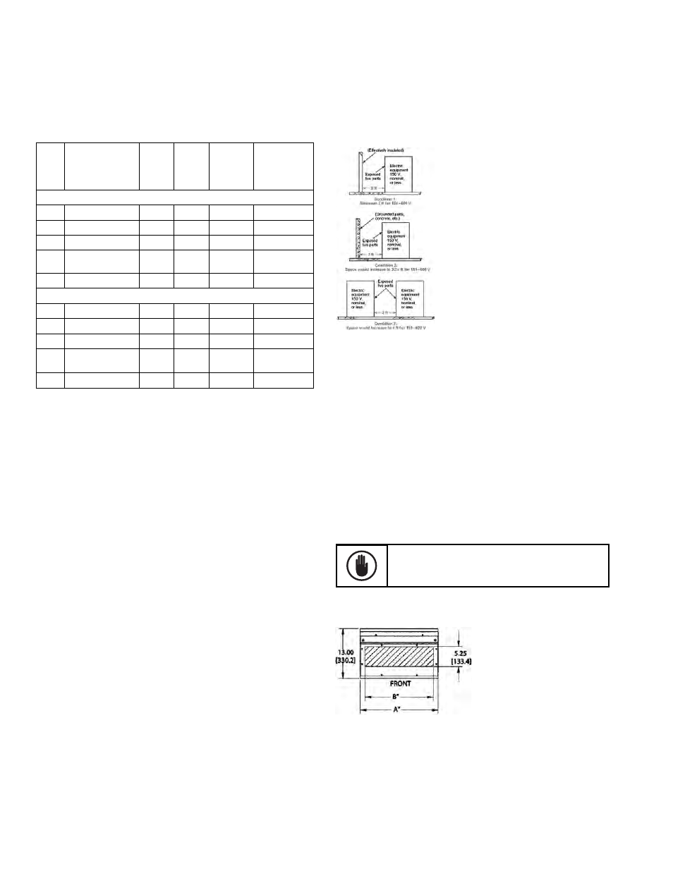
Installation of Top Entry Conduits
After the motor control center is in place and leveled, and
the sections are joined together, conduits can be brought
into the tops of sections as required. Figure 15 and
Figure 16 show the conduit entry space available at the
tops of standard sections. Refer to drawings furnished by
GE for deviations on specific installations. Note: Top rear
entrance should only be used with full rear accessibility.
Figure 15. Top conduit entry space for 13-inch sections
Always remove top cover plates when drilling
holes. This prevents small metal chips from falling
into the panel and cause serious damage.
Amps
Main Bus Splice
Assembly Kit
Bars/
Phase
Copper
Size
(in.)
(thick x
width)
SC Rating
600V Max.
(sym.
amps)
Splice
Instruction
Drawing*
Standard Splicing
600
110C1735G1SM
1
1/4 x 2 65K
110C1258TG1
800
110C1735G4SM
1
3/8 x 2 65K
110C1256TG1
1200 110C1735G7SM
1
1/2 x 2 100K
110C1253TG1
1600/
2000
110C1735G12SM 2
1/2 x 2 100K
110C1263TG1
2500 110C1735G13SM 2
1/2 x 2 100K
110C1785TG1
N3R and Spacer Shells
600
110C1735G14SM 1
1/4 x 2 65K
110C1258TG1
800
110C1735G15SM 1
3/8 x 2 65K
110C1256TG1
1200 110C1735G16SM 1
1/2 x 2 100K
110C1253TG1
1600/
2000
110C1735G17SM 2
1/2 x 2 100K
110C1263TG1
2500 110C1735G13SM 2
1/2 x 2 100K
110C1263TG1
Evolution Series E9000 Installation & Maintenance Guide