Picotlynx, 6a: non-isolated dc-dc power modules, Data sheet – GE Industrial Solutions PicoTLynx 6A User Manual
Page 14: Ω − = k vo rtrim 6 . 0 2 . 1, Vout
GE
Data Sheet
PicoTLynx
TM
6A: Non-Isolated DC-DC Power Modules
2.4Vdc –5.5Vdc input; 0.6Vdc to 3.63Vdc output; 6A Output Current
September 11, 2013
©2013 General Electric Company. All rights reserved.
Page 14
0
1
2
3
4
5
6
0.5
1
1.5
2
2.5
3
3.5
4
Output Voltage (V)
In
p
u
t V
o
lt
ag
e (
v)
Upper Limit
Lower Limit
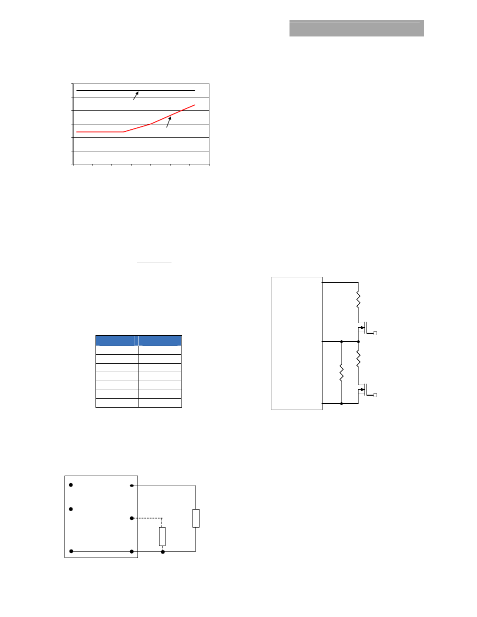
Figure 40. Output Voltage vs. Input Voltage Set Point Area plot
showing limits where the output voltage can be set for
different input voltages.
Without an external resistor between Trim and GND pins, the
output of the module will be 0.6Vdc. To calculate the value of
the trim resistor, Rtrim for a desired output voltage, use the
following equation:
(
)
Ω
−
=
k
Vo
Rtrim
6
.
0
2
.
1
Rtrim is the external resistor in kΩ
Vo is the desired output voltage.
Table 1 provides Rtrim values required for some common output
voltages.
Table 1
V
O, set
(V)
Rtrim (KΩ)
0.6 Open
1.0 3.0
1.2 2.0
1.5 1.333
1.8 1.0
2.5 0.632
3.3 0.444
By using a ±0.5% tolerance trim resistor with a TC of ±25ppm, a
set point tolerance of ±1.5% can be achieved as specified in the
electrical specification. The POL Programming Tool available at
www.lineagepower.com
under the Design Tools section, helps
determine the required trim resistor needed for a specific output
voltage.
V
O
(+)
TRIM
GND
R
trim
LOAD
V
IN
(+)
ON/OFF
Vout
Figure 41. Circuit configuration for programming output
voltage using an external resistor.
Remote Sense
The Pico TLynx
TM
6A modules have a Remote Sense feature to
minimize the effects of distribution losses by regulating the
voltage at the SENSE pin. The voltage between the SENSE pin
and VOUT pin must not exceed 0.5V. Note that the output
voltage of the module cannot exceed the specified maximum
value. This includes the voltage drop between the SENSE and
Vout pins. When the Remote Sense feature is not being used,
connect the SENSE pin to the VOUT pin.
Voltage Margining
Output voltage margining can be implemented in the Pico
TLynx
TM
6A modules by connecting a resistor, R
margin-up
, from
the Trim pin to the ground pin for margining-up the output
voltage and by connecting a resistor, R
margin-down
, from the Trim
pin to the Output pin for margining-down. Figure 42 shows the
circuit configuration for output voltage margining. The POL
Programming Tool, available at
www.lineagepower.com
under
the Design Tools section, also calculates the values of R
margin-up
and R
margin-down
for a specific output voltage and % margin.
Please consult your local Lineage Power technical
representative for additional details.
Vo
MODULE
GND
Trim
Q1
Rtrim
Rmargin-up
Q2
Rmargin-down
Figure 42. Circuit Configuration for margining Output
voltage.
Monotonic Start-up and Shutdown
The Pico TLynx
TM
6A
modules have monotonic start-up and
shutdown behavior for any combination of rated input voltage,
output current and operating temperature range.
Startup into Pre-biased Output
The 5.5V Pico TLynx
TM
6A modules can start into a prebiased
output as long as the prebias voltage is 0.5V less than the set
output voltage. Note that prebias operation is not supported
when output voltage sequencing is used.