Picotlynx, 6a: non-isolated dc-dc power modules, Data sheet – GE Industrial Solutions PicoTLynx 6A User Manual
Page 13: Feature descriptions
GE
Data Sheet
PicoTLynx
TM
6A: Non-Isolated DC-DC Power Modules
2.4Vdc –5.5Vdc input; 0.6Vdc to 3.63Vdc output; 6A Output Current
September 11, 2013
©2013 General Electric Company. All rights reserved.
Page 13
Feature Descriptions
Remote On/Off
The Pico TLynx
TM
6A modules feature an On/Off pin for remote
On/Off operation. Two On/Off logic options are available. In the
Positive Logic On/Off option, (device code suffix “4” see Ordering
Information), the module turns ON during a logic High on the
On/Off pin and turns OFF during a logic Low. With the Negative
Logic On/Off option, (no device code suffix see Ordering
Information), the module turns OFF during logic High and ON
during logic Low. The On/Off signal is always referenced to
ground. For either On/Off logic option, leaving the On/Off pin
disconnected will turn the module ON when input voltage is
present.
For positive logic modules, the circuit configuration for using the
On/Off pin is shown in Figure 38. When the external transistor Q1
is in the OFF state, Q2 is ON, the internal PWM Enable signal is
pulled low and the module is ON. When transistor Q1 is turned
ON, the On/Off pin is pulled low, Q2 is turned off and the internal
PWM Enable signal is pulled high through the 100K internal pull-
up resistor and the module is OFF.
Figure 38. Circuit configuration for using positive On/Off
logic.
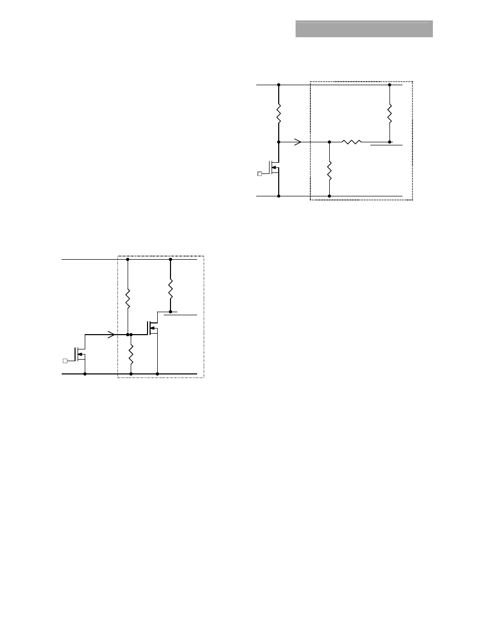
For negative logic On/Off modules, the circuit configuration is
shown in Fig. 39. The On/Off pin should be pulled high with an
external pull-up resistor (suggested value for the 2.4V to 5.5Vin
range is 3.6Kohms). When transistor Q1 is in the OFF state, the
On/Off pin is pulled high and the module is OFF. The On/Off
threshold for logic High on the On/Off pin depends on the input
voltage and its minimum value is V
IN
– 1.6V. To turn the module
ON, Q1 is turned ON pulling the On/Off pin low.
Figure 39. Circuit configuration for using negative On/Off
logic.
Over Current Protection
To provide protection in a fault (output overload) condition, the
unit is equipped with internal current-limiting circuitry and can
endure current limiting continuously. At the point of
current-limit inception, the unit enters hiccup mode. The unit
operates normally once the output current is brought back into
its specified range.
Over Temperature Protection
To provide protection in a fault condition, the unit is equipped
with a thermal shutdown circuit. The unit will shutdown if the
overtemperature threshold of 140
o
C is exceeded at the thermal
reference point T
ref
. The thermal shutdown is not intended as a
guarantee that the unit will survive temperatures beyond its
rating. Once the unit goes into thermal shutdown it will then
wait to cool before attempting to restart.
Input Undervoltage Lockout
At input voltages below the input undervoltage lockout limit, the
module operation is disabled. The module will begin to operate
at an input voltage above the undervoltage lockout turn-on
threshold.
Output Voltage Programming
The output voltage of the Pico TLynx
TM
6A module can be
programmed to any voltage from 0.6Vdc to 3.63Vdc by
connecting a resistor between the Trim and GND pins of the
module. Certain restrictions apply on the output voltage set
point depending on the input voltage. These are shown in the
Output Voltage vs. Input Voltage Set Point Area plot in Fig. 40.
The Upper Limit curve shows that the entire output voltage
range is available with the maximum input voltage of 5.5V. The
Lower Limit curve shows that for output voltages of 1.8V and
higher, the input voltage needs to be larger than the minimum
of 2.4V.
100K
Q1
GND
PWM Enable
ON/OFF
VIN+
ON/OFF
_
+
I
V
MODULE
ON/OFF
20K
Q2
20K
100K
Q1
GND
PWM Enable
ON/OFF
VIN+
ON/OFF
_
+
V
I
MODULE
Rpullup
ON/OFF
2.05K
20K