Through-hole lead-free soldering information – GE Industrial Solutions FLT012A0-SZ User Manual
Page 9
Data Sheet
February 9, 2012
FLT012A0Z/FLT012A0-SZ Input Filter Modules
75Vdc Input Voltage Maximum, 12A Output Current Maximum
LINEAGE
POWER
9
minimum of 12 months from the bag seal date, when
stored at the following conditions: < 40° C, < 90%
relative humidity.
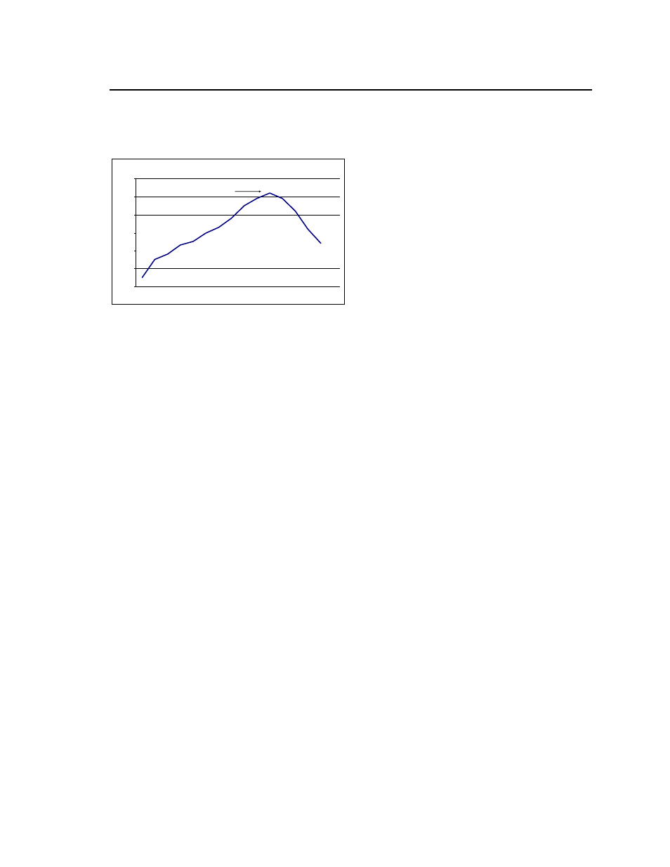
Per J-STD-020 Rev. C
0
50
100
150
200
250
300
Reflow Time (Seconds)
R
efl
ow
Te
m
p (°
C)
Heating Zone
1°C/Second
Peak Temp 260°C
* Min. Time Above 235°C
15 Seconds
*Time Above 217°C
60 Seconds
Cooling Zone
4°C/Second
Figure 15. Recommended linear reflow profile
using Sn/Ag/Cu solder.
Post solder Cleaning and Drying
Considerations
Post solder cleaning is usually the final circuit-board
assembly process prior to electrical board testing. The
result of inadequate cleaning and drying can affect
both the reliability of a power module and the
testability of the finished circuit-board assembly. For
guidance on appropriate soldering, cleaning and
drying procedures, refer to Lineage Power Board
Mounted Power Modules: Soldering and Cleaning
Application Note.(AN04-001)
Through-Hole Lead-Free Soldering
Information
The RoHS-compliant through-hole products use the
SAC (Sn/Ag/Cu) Pb-free solder and RoHS-compliant
components. They are designed to be processed
through single or dual wave soldering machines. The
pins have an RoHS-compliant finish that is compatible
with both Pb and Pb-free wave soldering processes.
A maximum preheat rate of 3
°C/s is suggested. The
wave preheat process should be such that the
temperature of the power module board is kept below
210
°C. For Pb solder, the recommended pot
temperature is 260
°C, while the Pb-free solder pot is
270
°C max. Not all RoHS-compliant through-hole
products can be processed with paste-through-hole
Pb or Pb-free reflow process. If additional information
is needed, please consult with your Lineage Power
representative for more details.