Lineage power 6 – GE Industrial Solutions FLT012A0-SZ User Manual
Page 6
Data Sheet
February 9, 2012
FLT012A0Z/FLT012A0-SZ Input Filter Modules
75Vdc Input Voltage Maximum, 12A Output Current Maximum
LINEAGE
POWER
6
C HASSIS GR OUN D
VI(+)
VI(-)
VO(+)
VO(-)
CASE
DC/DC
CONVERTER
MODULE
C1
FILTER
MODULE
VI(+)
VI(-)
C3
C2
C 4
C5
SHIELD PLANE
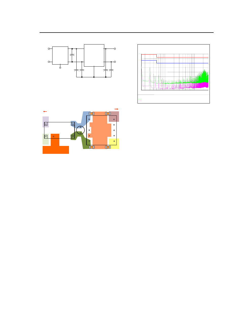
Figure 7. Schematic diagram showing
recommended connection of the FLT012A0 filter
module with metal-cased DC/DC converter
modules.
C
2
Load
DC/DC
CONVERTER
C
3
C
1
V
I
+ V
O
+
V
O
-
V
I
-
CASE
C
5
C
4
SHIELD
PLANE
Input
V
IN
-
V
IN
+
CHASSIS
GROUND
V
O
+
V
O
−
FLT012A0
MODULE
GND
Figure 8. Diagram showing recommended layout
of the FLT012A0 filter module with metal-case
DC/DC converter modules.
Example Data Showing Results using
the FLT012A0 Modules
Figure 9 shows example results obtained using a
QBVW033 DC/DC converter module with the
FLT012A0 filter module. The QBVW033 module is
operated at an input voltage of 48V and output
loading corresponding to an input current of 8.7A, a
level close to the 12A capability of the FLT012A0 filter
module. Board capacitance was as per
recommendations in the QBVW033 datasheet. The
results show that the filter module is capable of
meeting EN55022 Class A limits with 11 margin.
Figure 9. Experimental results showing
conducted EMI measured using a FLT012A0
module with a QBVW033 DC/DC converter.
0
10
20
30
40
50
60
70
80
Level [dBµV]
150k
300k
500k
1M
2M
3M
5M
7M
10M
30M
Frequency [Hz]
+
+
+
+
+
+
++
x
x
x
x
x
xxx
x
MES CE1220111019_fin QP
+
MES CE1220111019_fin AV
MES CE1220111019_pre PK
MES CE1220111019_pre AV