Cable installation – GE Industrial Solutions Cable Operator Mechanisms for Thermal-Magnetic E150 and Spectra SE150, SF250, and SG600 MCCBs User Manual
Page 5
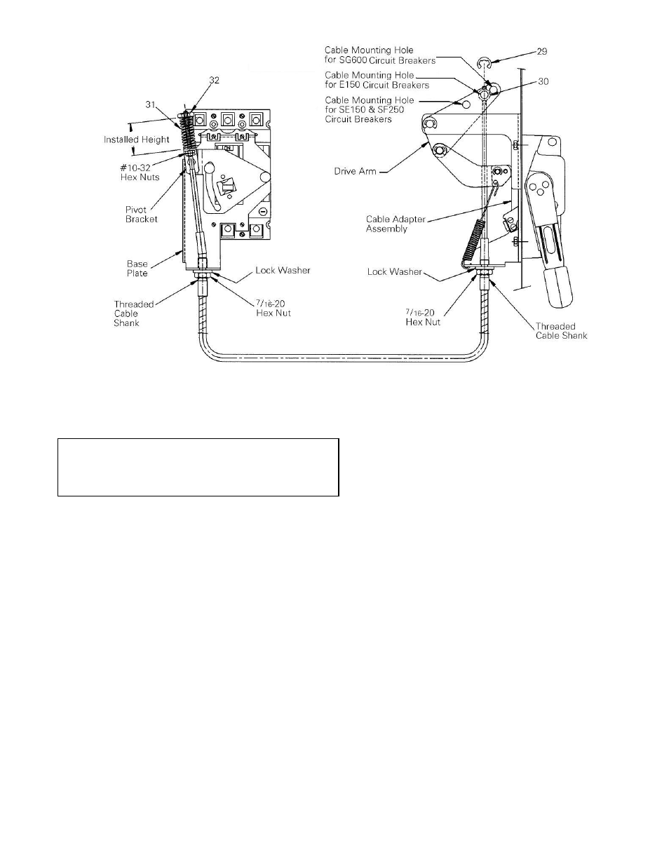
Figure 7. Cable Installation
Cable Installation
WARNING:
Danger of electrical shock or injury. Turn
OFF power ahead of the device before accessory
installation.
DO NOT
remove circuit protective devices
until the power is turned OFF.
Use the following procedure to first install one end of the
operating cable to the operating handle, then the other
end to the breaker operating mechanism.
1. Slide a
7
/
16
-20 hex nut onto the end of the cable with
the #10-32 x
7
/
8
" thread. Install the nut onto the
threaded cable shank beyond the groove at the
middle of the shank. Install a
7
/
16
" lock washer onto
the hex nut. Screw the cable guide pin [30] onto the
same end of the cable all the way. Do not tighten.
2. Place the operating handle in the OFF position.
Position the cable behind the handle drive arm
linkage. Insert the groove of the cable (middle of the
cable shank threads) into the slot at the bottom of
the cable operator assembly. Tighten the
7
/
16
" hex
nut against the cable adapter assembly until it is
snug. Insert the cable guide pin [30] into the proper
mounting hole in the drive arm, as shown in Figure
7. Snap an E-ring [29] into the groove of the guide
pin [30].
3. Slide a
7
/
16
-20 hex nut over the cable end with the
#10-32 x 3" thread. Install the nut onto the threaded
cable shank beyond the groove at the middle of the
shank. Install a
7
/
16
" lock washer onto the hex nut.
Thread two #10-32 hex nuts approximately 2
3
/
4
”
onto the threaded end of the cable. Rotate the pivot
bracket into position, as shown in Figure 7, and
insert the end of the cable through the pivot bracket.
Insert the groove of the cable into the slot on the
base plate. Tighten the
7
/
16
-20 hex nut against the
base plate flange until snug. With the breaker in the
OFF position, move the #10-32 hex nut up on the
cable shaft against the pivot bracket. Note the
position of the pivot bracket in Figure 7.
4. Verify that the power to the circuit breaker has been
turned off. Move the operating handle on the circuit
breaker to the ON position. Place the spring [31]
over the cable end. Thread the spring retainer [32]
onto the end of the cable and tighten to the installed
height of 1
7
/
16
".
Do not overtighten the retainer.
5. Move the operating handle ON and then OFF. If the
breaker does not turn ON, then, with the handle in
the OFF position, adjust the #10-32 hex nut toward
the pivot bracket until the breaker turns ON.
6. Trip the circuit breaker by pushing the TRIP button.
Move the operating handle to the OFF/RESET
position, then to ON. If the breaker resets, set the
spring retainer to the installed height of 1
7
/
16
". Lock
both #10-32 hex nuts against the pivot bracket.
7. If the breaker does not reset, back off the #10-32 hex
nuts, tighten the spring retainer, and repeat steps 5,
6, and 7.