GE Industrial Solutions Cable Operator Mechanisms for Thermal-Magnetic E150 and Spectra SE150, SF250, and SG600 MCCBs User Manual
Page 4
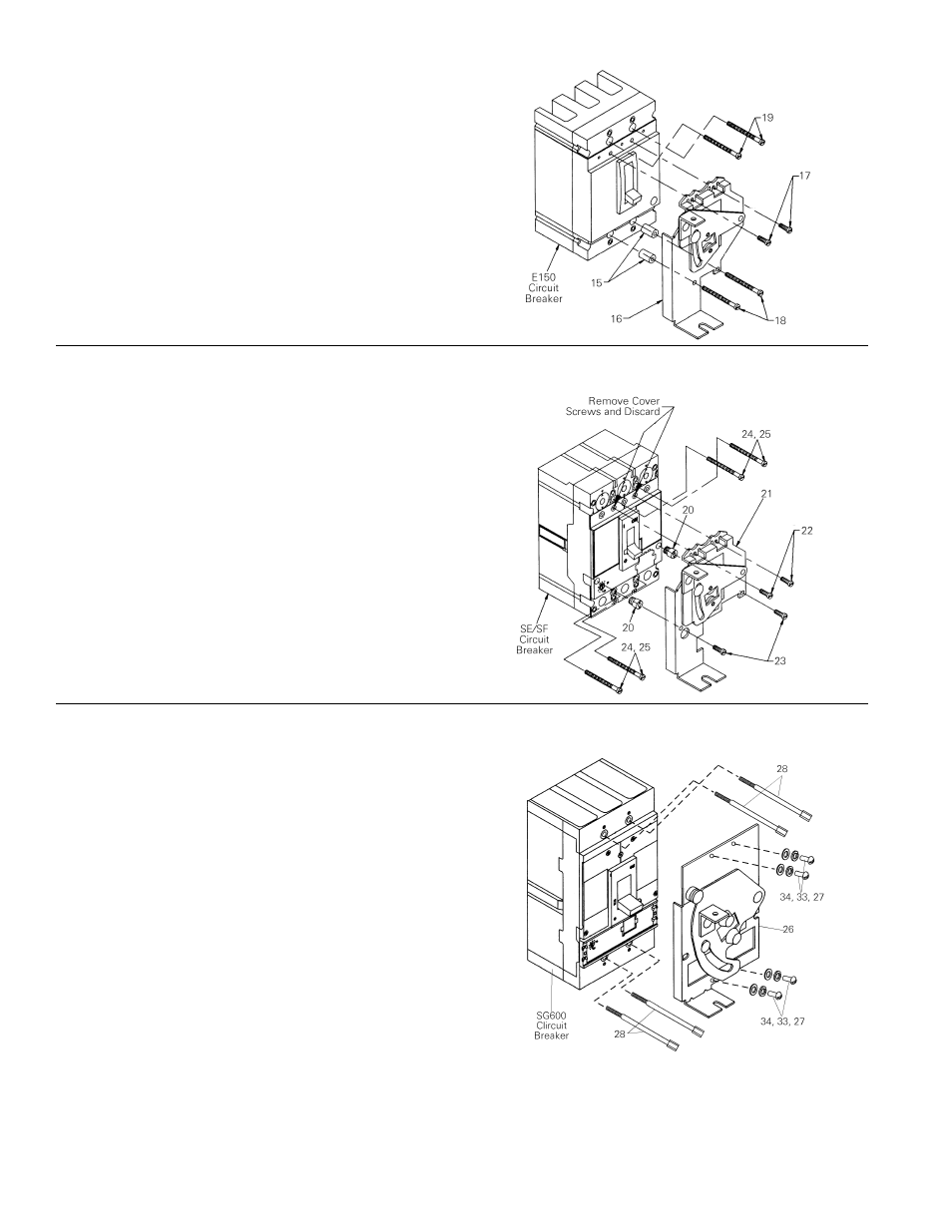
Figure 4. Installation of SCOM1A
Install the E150 circuit breaker in the panel with two #8-
32 x 2
3
/
4
" screws [19] on the line end of the circuit
breaker.
Place the spacers [15] into the counterbore on the load
end of the E150 breaker mounting holes. With the
breaker in the OFF position, place the breaker operating
mechanism [16] on top of the breaker cover with the
breaker handle extending through the mechanism pivot
plate. Secure the operating mechanism to the breaker
on the line side with two thread-cutting screws [17].
Secure the operating mechanism and the circuit breaker
on the load side to the panel surface with two #8-32 x 4"
screws [18].
Figure 5. Installation of SCOM1EF
Install an SE150 circuit breaker in the panel with four
#8-32 x 2
3
/
4
" screws [24]. Install an SF250 circuit
breaker in the panel with four #12-24 x 3
3
/
4
" screws
[25].
Thread the spacers [20] into the counterbore (
5
/
16
"-dia.
holes) on the load end of the SE150 or SF250 circuit
breaker. Remove the two breaker cover screws on the
line end of the breaker, as shown, and discard. With the
circuit breaker in the OFF position, place the breaker
operating mechanism [21] on top of the breaker cover
with the breaker handle extending through the
mechanism pivot plate. Secure the operating
mechanism to the breaker line side with two 3.5 x 10
mm metric screws [22]. Secure the mechanism on the
load side with two #8-32 screws [23], threading them
into the spacers [20].
Figure 6. Installation of SCOM1G
1. Mount the circuit breaker to the panel using the
four special mounting bolts [28]. Thread size is
#10-32.
2. Secure the mechanism to the breaker using four
#10-32 screws [27], lock washers [33], and flat
washers [34].