GE Industrial Solutions Cable Operator Mechanisms for Thermal-Magnetic E150 and Spectra SE150, SF250, and SG600 MCCBs User Manual
Page 2
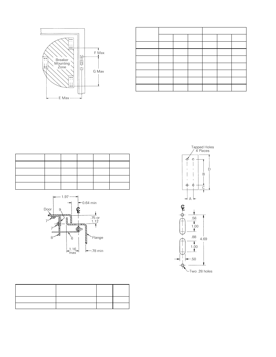
Table 2. Circuit Breaker Mounting-Zone Dimensions
To determine maximum mounting dimensions for 60-
inch through 120-inch-long operating cables, add the
respective additional lengths to the 48-inch cable
maximum dimensions. (For example, add 12 inches to E,
F, and G dimensions for 60-inch cable length.)
Maximum Dimensions in Inches
Enclosure
36” Cable
48” Cable
Depth
E* F G E* F G
8 13.5
4.0
15.0
25.5 16.0 27.0
10 13.0
5.0
14.8
25.0 17.0 26.8
12 12.8
6.0
14.5
24.8 17.0 26.5
16 10.5
4.5
14.2
22.5 16.5 26.2
18 8.5
3.5
12.6
20.5 15.5 24.6
20
— 0.5 10.0 22.0 15.0 24.0
24
— — —
19.5
14.0
22.0
* Maximum E dimension only if F = 4.5”.
When cable is installed, the minimum cable bend radius
should not be less than 3 inches. The minimum cable
bending requirement must be met to ensure a safe
operating environment.
Table 3. Circuit Breaker Mounting Dimension
Breaker Type
A
B
C
D
Tap Size
E150 1.38
4.88
0.72 6.31 8-32
SE150 1.38
4.88
0.72 6.51 10-32
SF250
1.38 7.75 1.19 10.12 12-24
SG600 1.81
7.75
1.19 13.62 12-24
Figure 1. End view of flange and cover (right end shown).
Table 4. Handle Dimensions (see Figure 3)
NEMA 12
Handle Cat. No.
NEMA 4/4X
Handle Cat. No.
L
H
SCH1 SCH1X
6.04
2.38
SCH2, SCH2K
SCH2X, SCH2KX
9.38
3.00
Figure 2. Flange details.