Handle installation – GE Industrial Solutions Cable Operator Mechanisms for Thermal-Magnetic E150 and Spectra SE150, SF250, and SG600 MCCBs User Manual
Page 3
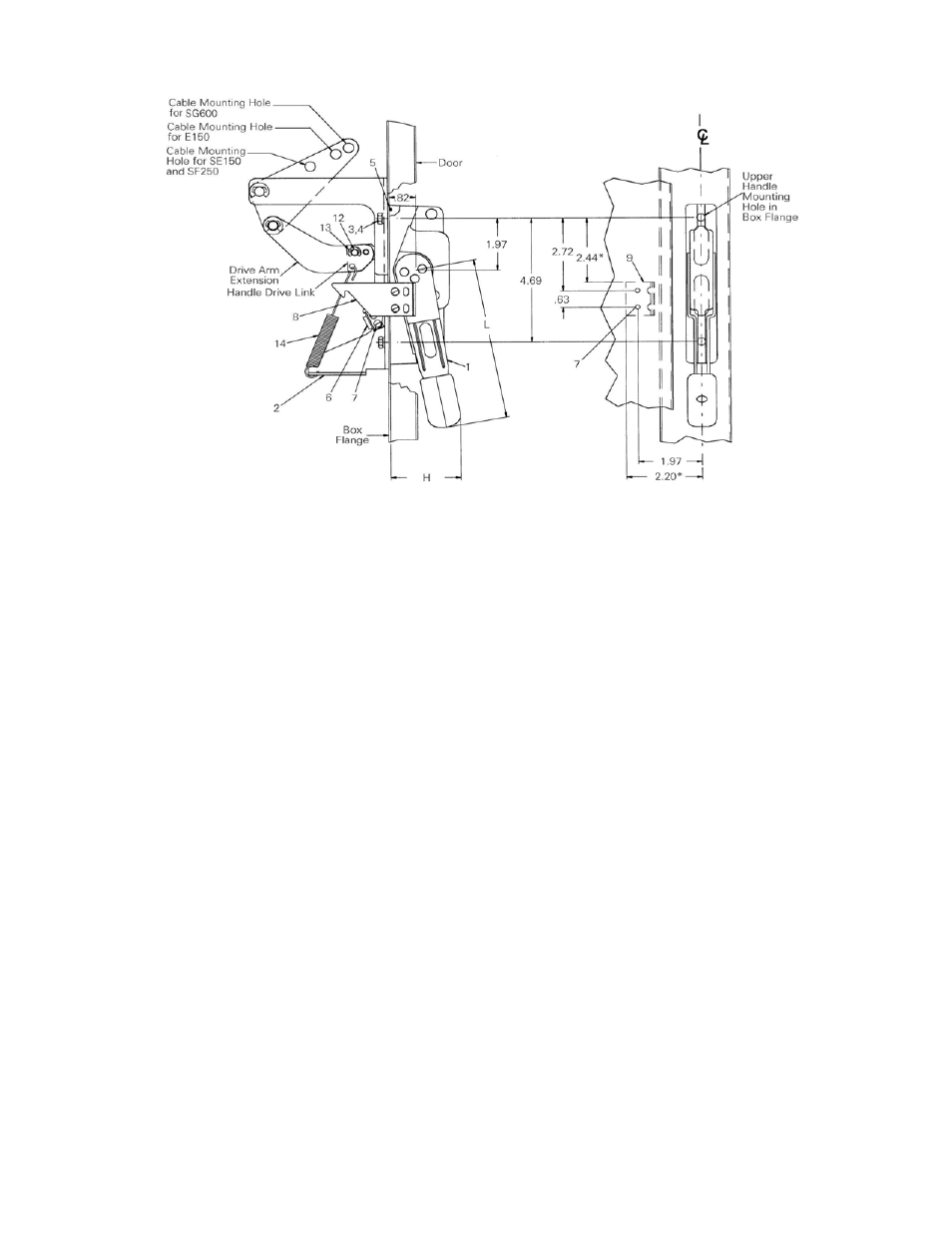
Figure 3. Handle Installation.
Handle Installation
1. Referring to Figure 1, Figure 2, and Figure 3,
determine the location of the handle on the flange
of the enclosure. The handle can be mounted on
either the right or left side of the enclosure.
2. If the flange is not provided with handle holes and
slots, drill these as shown in Figures 1 and 2. Remove
any burrs.
3. Position the O-ring [5] in the groove in the handle.
Assemble the handle [1] and the cable adapter
assembly [2] to the flange of the enclosure with two
1
/
4
-20 x
5
/
8
" hex-head screws [3] and lock washers
[4]. Tighten the screws to 35–45 in-lb.
4. Assemble the interlock blade [6] to the handle with
two #8-32 sems screws [7], as shown in Figure 1.
5. Assemble the drive arm extension to the handle drive
link with the connecting pin [12]. Secure the
connection with an E-ring [13], as shown in Figure 3.
6. Attach one end of the handle-return spring [14] to
the hole in the drive link and the drive arm
extension. Attach the other end to the hole in the
lower flange of the cable adapter assembly, as
illustrated in Figure 3.
7. Drill and tap two #8-32 holes in the cover, as shown
in Figures 1 and 3. Assemble the interlock bracket [9]
to the cover with two #8-32 sems screws [7] from
inside the door. Alternatively, the bracket may be
welded to the cover, using the dimensions noted with
an asterisk (*) in Figure 3, to locate the upper-left
corner of the bracket, as illustrated in Figure 1.
8. Assemble the interlock hook [8] to the interlock
bracket [9] with two #8-32 sems screws [7]. Use the
lower set of holes in the hook for a door with a
3
/
4
-
inch turned edge (as shown) or the upper set of
holes if the door has a 1.
1
/
8
-inch turned edge.
9. With the handle in the OFF position, attempt to close
the door. If the interlock blade interferes with the
interlock hook,
DO NOT
force the door closed.
Loosen the two #8-32 screws [7] and move the
interlock hook upward. The door should close
without interference. Attempt to turn the handle ON;
if the handle turns ON, loosen the two #8-32 screws
[7], secure the interlock hook, and move the hook
toward the bottom of the enclosure to provide more
depression of the interlock blade, thus preventing
the handle from engaging.
10. As the handle is moved to the ON position, the
interlock hook should engage the interlock blade,
preventing the door from opening unless the handle
interlock is manually disengaged by rotating
(clockwise) the interlock defeat button with a flat-
blade screw driver on the handle [1]. If the door can
be opened with the handle in the ON position
without having to defeat the interlock blade, readjust
the interlock hook downward and repeat steps 9 and
10.
11. Turn the handle to the OFF position. You should be
able to open the door. Note that if vault-type
interlock hardware (GE Cat. No. TDV1) or a similar
assembly has been installed, the door hardware must
first be defeated.
12. Proceed with installation of the drive cable and the
breaker operating mechanism per the instructions.