Step 3 – install the handle operating mechanism – GE Industrial Solutions Record Plus Cable Operating Mechanism: FC100, FE250 User Manual
Page 5
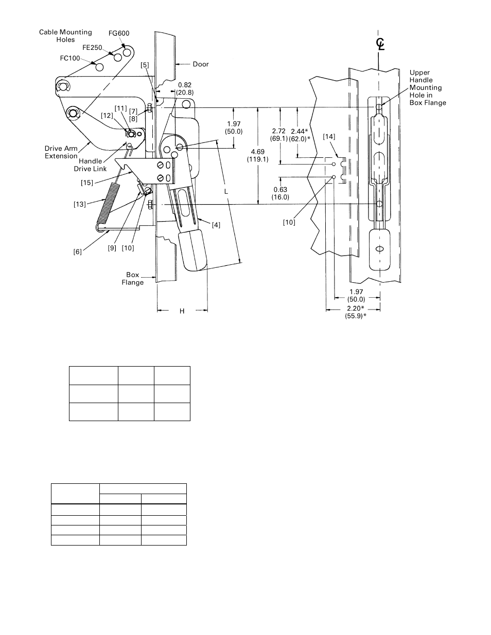
Figure 8. Handle mechanism installation.
Step 3 – Install the Handle
Operating Mechanism
Handle L,
in.
(mm)
H, in.
(mm)
This procedure is illustrated in Figure 2, Figure 5,
Figure 6, Figure 7, and Figure 8. The handle
dimensions, as shown in Figure 8, are listed in
Table7.
FCNHM1 /
FCNHM3
6.04
(153.4)
2.38
(60.5)
FCNHM2 /
FCNHM4
9.38
(238.3)
3.00
(76.2)
1.
In coordination with the location of the breaker,
select the mounting location for the handle
operating mechanism on the flange of the
enclosure. The handle can be mounted on either
the right or the left side of the enclosure.
Table 7. Handle dimensions shown in Figure 8.
2.
If the enclosure flange does not have handle
mounting holes and slots, drill these as shown in
Figure 5 and Figure 6.
3.
Position the O-ring [5] in the groove in the
handle, as shown in Figure . Assemble the handle
[4] and the cable adapter assembly [6] to the
flange of the enclosure with two 1/4-20 x 5/8"
screws [7] and lock washers [8]. Tighten the
screws to torque given as per Table 8.
4.
Attach the interlock blade [9] to the handle with
two #8-32 SEMS screws [10], as shown in Figure
5.
Torque
Screw Size
lb-in N-m
#8-32
16 to 20 1.8 to 2.25
#10-32
27 to 32 3.0 to 3.6
#1/4-20
40 to 50 4.5 to 5.6
Table 8. Tightening torque details
.