Step 2 – install the breaker operating mechanism – GE Industrial Solutions Record Plus Cable Operating Mechanism: FC100, FE250 User Manual
Page 3
Step 2 – Install the Breaker
Operating Mechanism
36-Inch Cable (SC3L) 48-Inch Cable (SC4L)
This procedure is illustrated in Figure 2, Figure 3,
and Figure 4a and 4b.
Enclosure
Depth, in.
E F G E F G
1.
In coordination with the intended location of the
handle operating mechanism, select the
mounting location for the breaker.
13.5
(343)
4.0
(102)
15.0
(381)
25.5
(648)
16.0
(406)
27.0
(686)
8
illustrates the zone in which the breaker can be
mounted to meet the cable-bending requirement
and
13.0
(330)
5.0
(127)
14.8
(376)
25.0
(635)
17.0
(432)
26.8
(681)
10
12.8
(325)
6.0
(152)
14.5
(368)
24.8
(630)
17.0
(432)
26.5
(673)
12
Table 5 lists the maximum dimensions for
various enclosure depths, mounting locations,
and cable lengths. To determine maximum
mounting dimensions for 60-inch through 120-
inch-long operating cables, add the respective
additional lengths to the 48-inch cable maximum
dimensions. (For example, add 12 inches to E, F,
and G dimensions for a 60-inch cable length.)
When the cable is installed, the minimum
permissible cable bend radius is 3 inches. This
requirement must be met to ensure a safe
operating environment.
10.5
(267)
4.5
(114)
14.2
(361)
22.5
(572)
16.5
(419)
26.2
(665)
16
8.5
(216)
3.5
(89)
12.6
(320)
20.5
(521)
15.5
(394)
24.6
(625)
18
2.
Drill and tap the mounting holes for the breaker
according to the pattern shown in Figure 3. The
dimensions and hole sizes are listed in Table 6.
3.
Mount the breaker to the enclosure using the
four screws [2] (as per table 1) supplied with the
breaker operating mechanism and tighten the
screws to torque given as per Table 8.
4.
Place the breaker operating mechanism [1] over
the breaker, with the breaker operating handle
extending through the slot in the mechanism
slider, as shown in Figure 4a and 4b. Secure the
mechanism to the breaker with the four screws
[3] supplied (as per Table 1). Tighten the screws
to torque given as per Table 8. These screws
mount into the tapped holes in the heads of the
breaker mounting screws [2] installed in the
previous step.
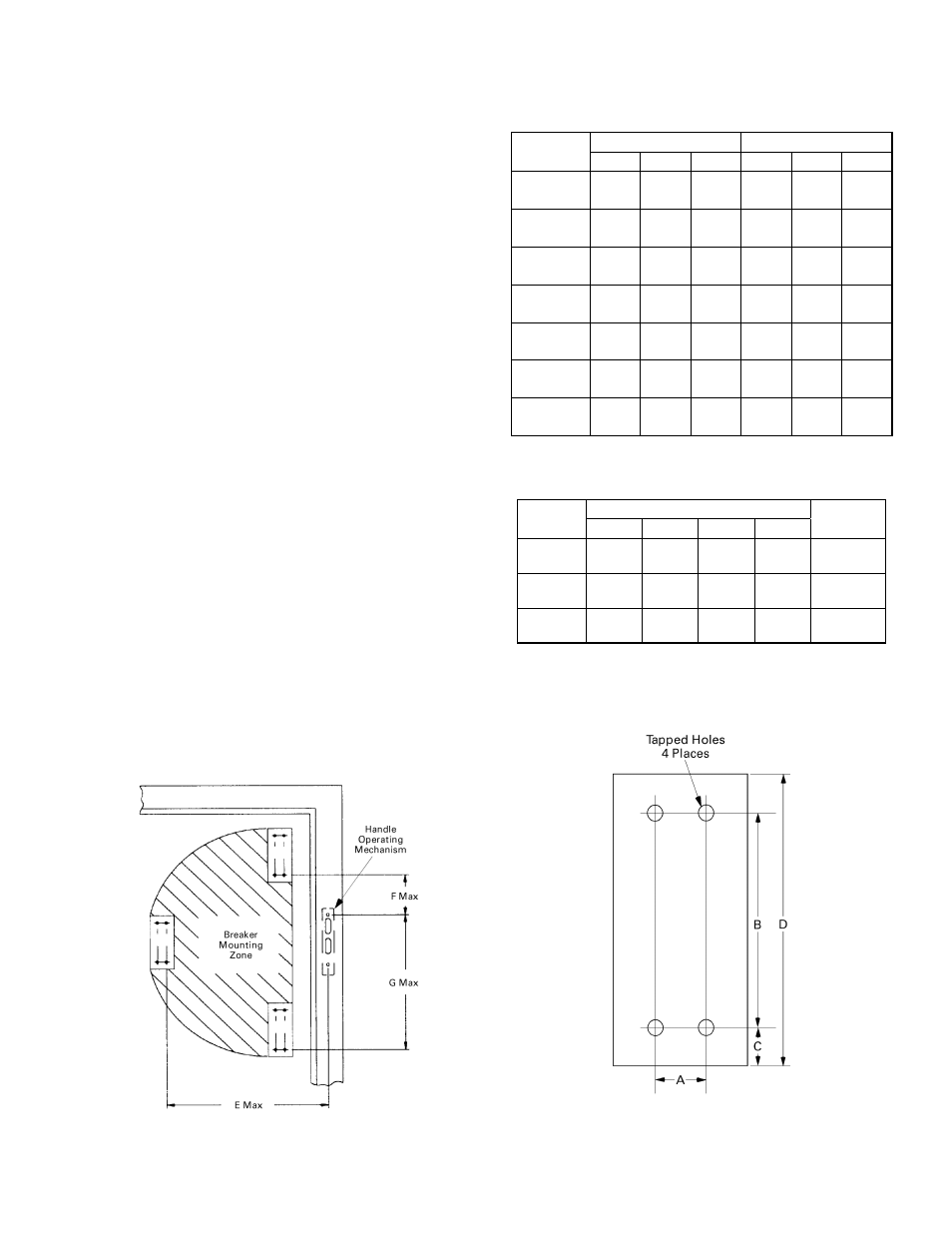
Figure 2. Circuit breaker mounting zone dimensions.
20 —
0.5
(13)
10.0
(254)
22.0
(559)
15.0
(381)
24.0
(610)
24 —
—
—
19.5
(495)
14.0
(356)
22.0
(559)
Table 5. Maximum lengths in inches (mm) for dimensions
illustrated in Figure 2.
Dimension, in. (mm)
Breaker
Frame
A B C D
Mounting
Screw
1.0
(25.4)
4.98
(126.5)
0.69
(17.5)
6.36
(161.5)
FC100
#8-32
1.38
(35.0)
4.94
(125.5)
0.87
(22.0)
6.69
(170.0)
FE250
#10-32
1.77
(45.0)
7.87
(198.1)
1.22
(31.0)
10.31
(261.9)
FG600
#12-24
Table 6. Dimensions for breaker mounting hole pattern,
shown in Figure 3.
Figure 3. Breaker mounting hole pattern.