Step 1 – unpack and inspect product description – GE Industrial Solutions Record Plus Cable Operating Mechanism: FC100, FE250 User Manual
Page 2
Step 1 – Unpack and Inspect
Product Description
Unpack the cable operator components and
inspect for damage. Verify that all parts are
supplied, as listed in Table 2, Table 3, and Table 4.
Note that the numbers in brackets in the following
figures and installation instructions refer to the
item numbers in these tables.
GE Cable Operating Mechanisms, illustrated in
Figure 1, are suitable for application with GE
circuit breakers mounted in a wide variety of
flanged enclosure types and sizes. The catalog
numbers and appropriate applications for the
available handle operating mechanisms, breaker
operating mechanisms, and cables are listed in
Table 1.
Check Table 4 to verify that the handle assembly,
cable, and breaker operating mechanism you have
are correct for the job. Check Figure 2 and Table 5
to ensure that the cable is long enough to reach
the breaker and that the 3-inch minimum bending
radius requirement is not violated.
Flange-mounted handle assemblies are available
for NEMA Type 1, 3R, 12, or 13 enclosures in either
6-inch (model FCNHM1) or 10-inch handle
lengths (model FCNHM2). Corresponding
assemblies, FCNHM3 and FCNHM4, are available
for NEMA Type 4/4X enclosures. Handle
assemblies are suitable for either left- or right-
flange operation.
Description
Item
QTY
FCNBM FENBM
1 Mechanism
Mechanism
1
The handle assembly is combined with one of
eight operating cables, with lengths from 3 to 10
feet, to cover a broad range of breaker mounting
locations in the enclosure. The cable links the
handle assembly to the breaker-mounted operating
mechanism and transmits the mechanical force
and motion of the handle mechanism to the
breaker-mounted mechanism. The force and
motion are transmitted independent of the breaker
mounting plane or location relative to the location
of the handle assembly, provided only that the
bending radius of the cable is no less than 3 inches.
No mounting reinforcement of the breaker or
enclosure flange is required.
Screw,
#10-32 X 3.15"
2
Screw, #8-32 x 2.81"
4
Screw, #10-32 x 0.50"
3
Screw, #8-32 x 0.312"
4
Table 2. Parts included in the breaker operating mechanism kits.
Item Description Qty.
4 Handle
assembly
1
5 O-ring
1
6 Cable
adapter
assembly
1
7 Screw,
1
/
4
-20 x
5
/
8
" 2
8 Lock
washer,
1
/
4
" 2
9 Interlock
blade
1
SEMS screws, #8-32 x
3
/
8
"
10
6
The breaker operating mechanism mounts directly
to the face of the breaker and does not involve any
mounting interface with the enclosure. Standard
breaker mounting screws for tapped holes are
furnished with each mechanism to mount the
breaker in the enclosure.
11 Connecting
pin
1
12 Retaining
ring
1
13 Spring
1
14 Interlock
bracket
1
15 Interlock
hook
1
Installation of the handle assembly onto the
enclosure flange can be performed independently
from installation of the breaker operating
mechanism onto the circuit breaker and from
installation of the circuit breaker in the enclosure.
First, install the breaker into the enclosure, and
then mount the breaker operating mechanism on
the breaker and the handle operating mechanism
to the enclosure. Install the cable between the
handle assembly and the breaker mechanism as
the final step.
Table 3. Parts included in the handle mechanism kits.
Item Description Qty.
16 Cable
assembly
1
17 Hex
nut,
7
/
16
-20 2
18 Lock
washer,
7
/
16
" 2
19 Cable guide pin
1
20 Retaining
ring
1
21 Hex nut, #10-32
2
22 Spring
1
23 Spring
retainer
1
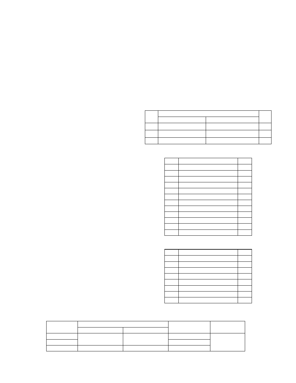
Table 4. Parts included in the cable kits.
Handle Operating Mechanism
Circuit
Breaker Type
Breaker Operating
Mechanism
Operating
Cable
NEMA 1, 3R, 12, 13
NEMA 4/4X
FC100 FCNBM
FCNHM1 FCNHM3
FE250
FENBM
SC3L to SC10L
FG600 FCNHM2 FCNHM4 FGNBM
Table 1. Catalog numbers of the cable operating mechanism components covered by these instructions.