Overview and features – GE Industrial Solutions ZNET901 User Manual
Page 3
■
■
Zenith Controls, Inc. ZNET900A, ZNET900B and ZNET901 Operation and Maintenance Manual (18R-1000)
1
■
■
Overview and Features
CONTROLS, INC.
R
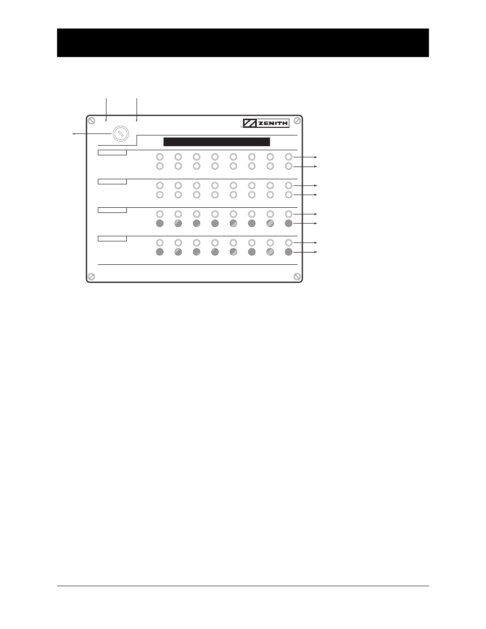
MONITOR
CONTROL
AUTOMATIC TRANSFER SWITCH
ANNUNCIATOR
POSITION
NORMAL
EMERGENCY
SOURCE
NORMAL
EMERGENCY
TIME DELAY
ACTIVE
BYPASS
TEST
IN PROGRESS
INITIATE
(HOLD UNTIL TRANSFER OCCURS)
1
2
3
4
5
6
7
8
Monitor
LEDs Only
Key
Switch
Control
Enables
Pushbuttons
(Key Removable Only in MONITOR Position)
Green LED ..................... Normal Position
Red LED ........................ Emergency Position
Green LED ..................... Normal Source
Red LED ........................ Emergency Source
Yellow LED .................... Active Time Delay
Black Push Button ........Bypass Time Delay (T or W)
Yellow LED .................... In Progress Test
Black Push Button ........Initiate Test
Customer Field Designation Label
KEY SWITCH —
The MONITOR position allows operation of LEDs only. (Key can be removed in this position) The CONTROL
position allows operation of LEDs and the pushbuttons. (Key cannot be removed in this position)
POSITION — Normal LED (Green)
Indicates that the corresponding Transfer Switch load is connected to the Normal source.
POSITION — Emergency LED (Red)
Indicates that the corresponding Transfer Switch load is connected to the Emergency source.
SOURCE — Normal LED (Green)
Indicates that the corresponding Transfer Switch has an acceptable Normal source.
SOURCE — Emergency LED (Red)
Indicates that the corresponding Transfer Switch has an acceptable Emergency source.
TIME DELAY
— Active LED (Yellow)
This flashing LED indicates that the corresponding Transfer Switch has a timer functioning. Timers monitored includes
all timers associated with delaying transfer in either direction. Note: Not available in closed transition mode.
TIME DELAY — Bypass Push Button
Will instantaneously lapse T or W timer whichever is timing concurrent with pushbutton activation. (Key Switch
must be in the Control position) Note: Not available in closed transition mode.
TEST — In Progress LED (Yellow)
Indicates the corresponding Transfer Switch is in a test mode. Indication will occur whether the test is initiated
at the annunciator or locally at the ATS.
TEST — Initiate Push Button
Begins a test sequence (power loss simulation) but must be held until transfer occurs. Transfer is complete
once the Emergency Position and Emergency Source LEDs are both illuminated. Releasing before test
is complete will cancel the test. (Key Switch must be in the Control position)