Physical description, Chapter 1 – introduction, Power leader modbus monitor – GE Industrial Solutions POWER LEADER ModBus Monitor User Manual
Page 13
POWER LEADER Modbus Monitor
Chapter 1 – Introduction
7
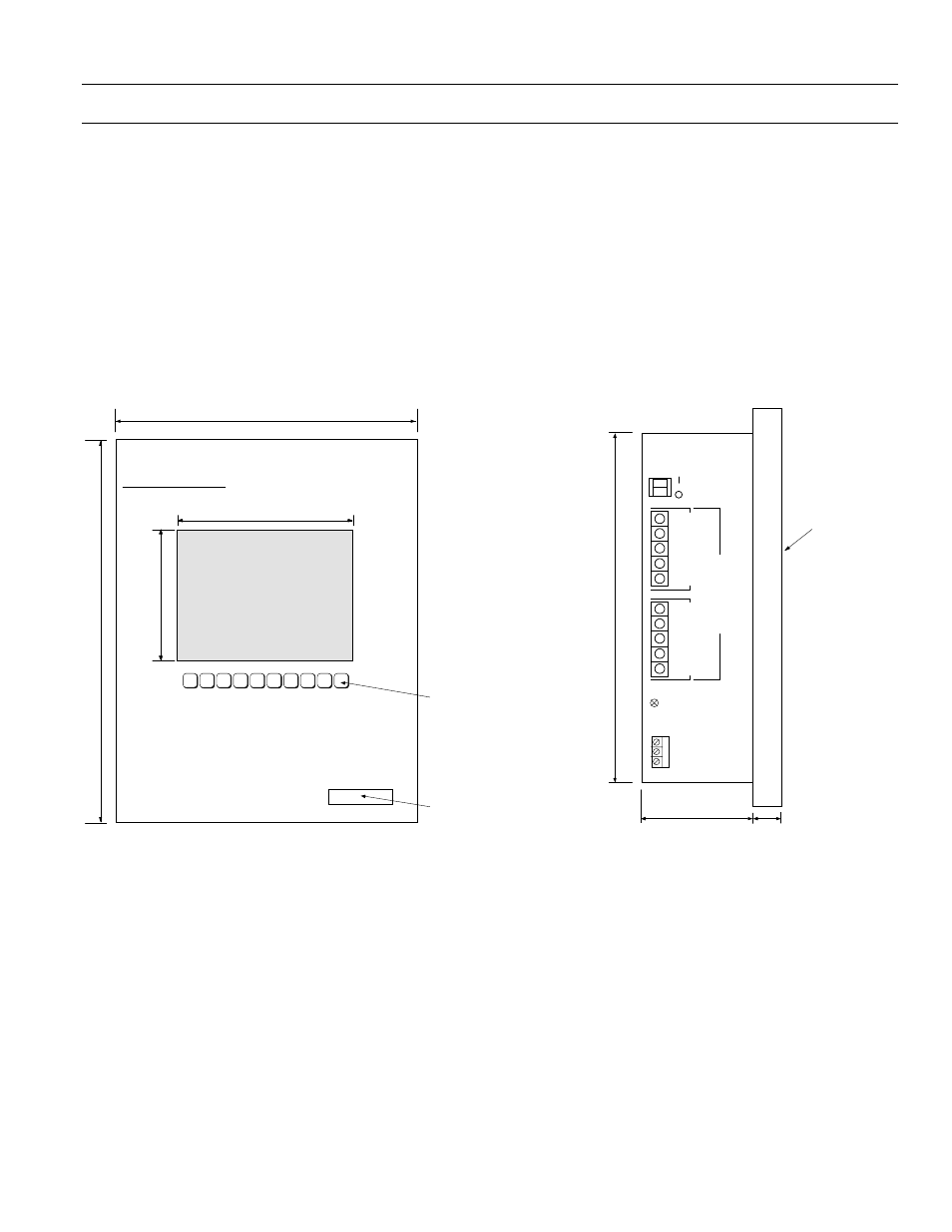
Physical Description
Figure 6 and Figure 7 show the dimensions of the
Monitor. The important features of the Monitor are listed
below:
•
The Monitor’s front panel display is used for viewing
device data and event messages during operation, for
diagnostics purposes, and for some very limited
configuration capabilities.
•
The keypad is located directly beneath the display. Ten
keys are used for navigating the menus of the Monitor.
•
A set of three terminals for AC or DC control power
input are provided on the side of the case.
•
A grounding screw is provided above the control power
connection.
•
Two five-terminal connectors on the side of the case
provide daisychained RS-485 input and output
connections to one or two Modbus segments.
•
The on/off switch for the Monitor is located on the side of
the case above the RS-485 connectors.
32:(5 /($'(5 0RGEXV 0RQLWRU
56 3RUW
NH\
PHPEUDQH
NH\SDG
LQ
',63/$<
LQ
LQ
LQ
Figure 6. Front view of Monitor, showing dimensions.
LQ
)URQW
LQ
&RQWURO 3RZHU ,QSXW
*5281'
LQ
32:(5 /($'(5
%
0RGEXV
0RQLWRU
+
1
*1'
127(
1RW WR VFDOH
&R
PP
XQ
LFD
WLR
QV
0RGE
XV
6HJP
HQW
%
0
RGE
XV
6HJP
HQW
$
,1
287
,1
287
6
6
Figure 7. Side view of the Monitor, showing dimensions and
connections.