2a picotlynx, Non-isolated dc-dc power modules, Data sheet – GE Industrial Solutions 2A PicoTLynx User Manual
Page 15
GE
Data Sheet
2A PicoTLynx
TM
: Non-Isolated DC-DC Power Modules
3Vdc –14Vdc input; 0.6Vdc to 5.5Vdc output; 2A Output Current
February 26, 2013
©2013 General Electric Company. All rights reserved.
Page 15
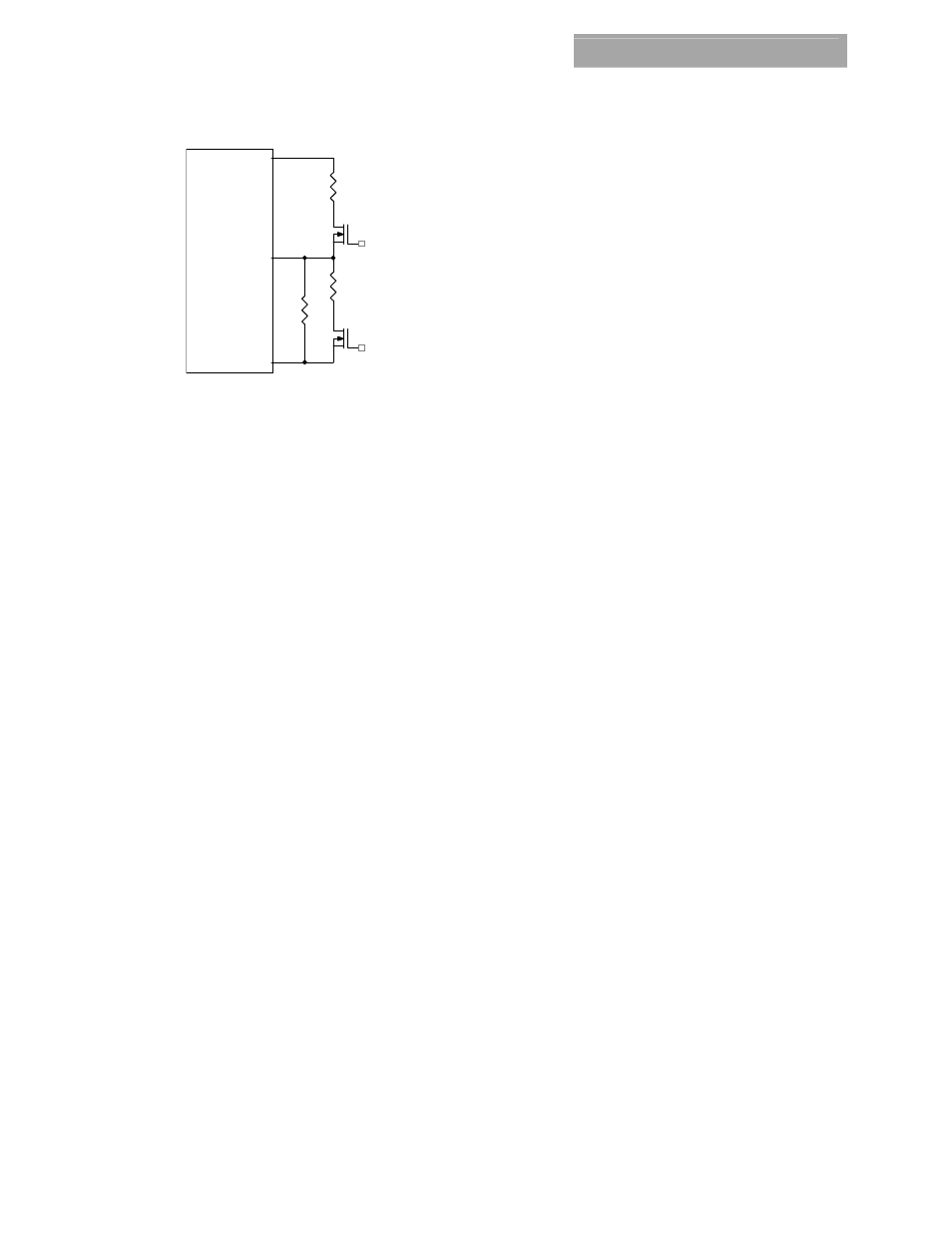
Vo
MODULE
GND
Trim
Q1
Rtrim
Rmargin-up
Q2
Rmargin-down
Figure 57. Circuit Configuration for margining Output
voltage.
Monotonic Start-up and Shutdown
The 12V PicoTLynx
TM
2A
modules have monotonic start-
up and shutdown behavior for any combination of rated
input voltage, output current and operating temperature
range.
Startup into Pre-biased Output
The 12V PicoTLynx
TM
2A modules can start into a
prebiased output as long as the prebias voltage is 0.5V
less than the set output voltage.
Power Good
The 12V PicoTLynx
TM
2A
modules provide a Power Good
(PGOOD) signal that is implemented with an open-drain
output to indicate that the output voltage is within the
regulation limits of the power module. The PGOOD signal
will be de-asserted to a low state if any condition such as
overtemperature, overcurrent or loss of regulation
occurs that would result in the output voltage going
±12.5% outside the setpoint value. The PGOOD terminal
should be connected through a pullup resistor
(suggested value 100K
Ω) to a source of 5VDC or lower.
Tunable Loop
TM
The 12V PicoTLynx
TM
2A modules have a new feature
that optimizes transient response of the module called
Tunable Loop
TM
.
External capacitors are usually added to the output of
the module for two reasons: to reduce output ripple and
noise (see Fig. 52) and to reduce output voltage
deviations from the steady-state value in the presence of
dynamic load current changes. Adding external
capacitance however affects the voltage control loop of
the module, typically causing the loop to slow down with
sluggish response. Larger values of external capacitance
could also cause the module to become unstable.
The Tunable Loop
TM
allows the user to externally adjust
the voltage control loop to match the filter network
connected to the output of the module. The Tunable
Loop
TM
is implemented by connecting a series R-C
between the SENSE and TRIM pins of the module, as
shown in Fig. 11. This R-C allows the user to externally
adjust the voltage loop feedback compensation of the
module.