2a picotlynx, Non-isolated dc-dc power modules, Data sheet – GE Industrial Solutions 2A PicoTLynx User Manual
Page 14: Ω − = k vo rtrim 6 . 0 0 . 6
GE
Data Sheet
2A PicoTLynx
TM
: Non-Isolated DC-DC Power Modules
3Vdc –14Vdc input; 0.6Vdc to 5.5Vdc output; 2A Output Current
February 26, 2013
©2013 General Electric Company. All rights reserved.
Page 14
continuously. At the point of current-limit inception, the unit
enters hiccup mode. The unit operates normally once the output
current is brought back into its specified range.
Overtemperature Protection
To provide protection in a fault condition, the unit is equipped
with a thermal shutdown circuit. The unit will shutdown if the
overtemperature threshold of 140
o
C is exceeded at the thermal
reference point T
ref
. The thermal shutdown is not intended as a
guarantee that the unit will survive temperatures beyond its
rating. Once the unit goes into thermal shutdown it will then
wait to cool before attempting to restart.
Input Undervoltage Lockout
At input voltages below the input undervoltage lockout limit, the
module operation is disabled. The module will begin to operate
at an input voltage above the undervoltage lockout turn-on
threshold.
Output Voltage Programming
The output voltage of the 12V PicoTLynx
TM
2A modules can be
programmed to any voltage from 0.6dc to 5.5Vdc by connecting
a resistor between the Trim and GND pins of the module.
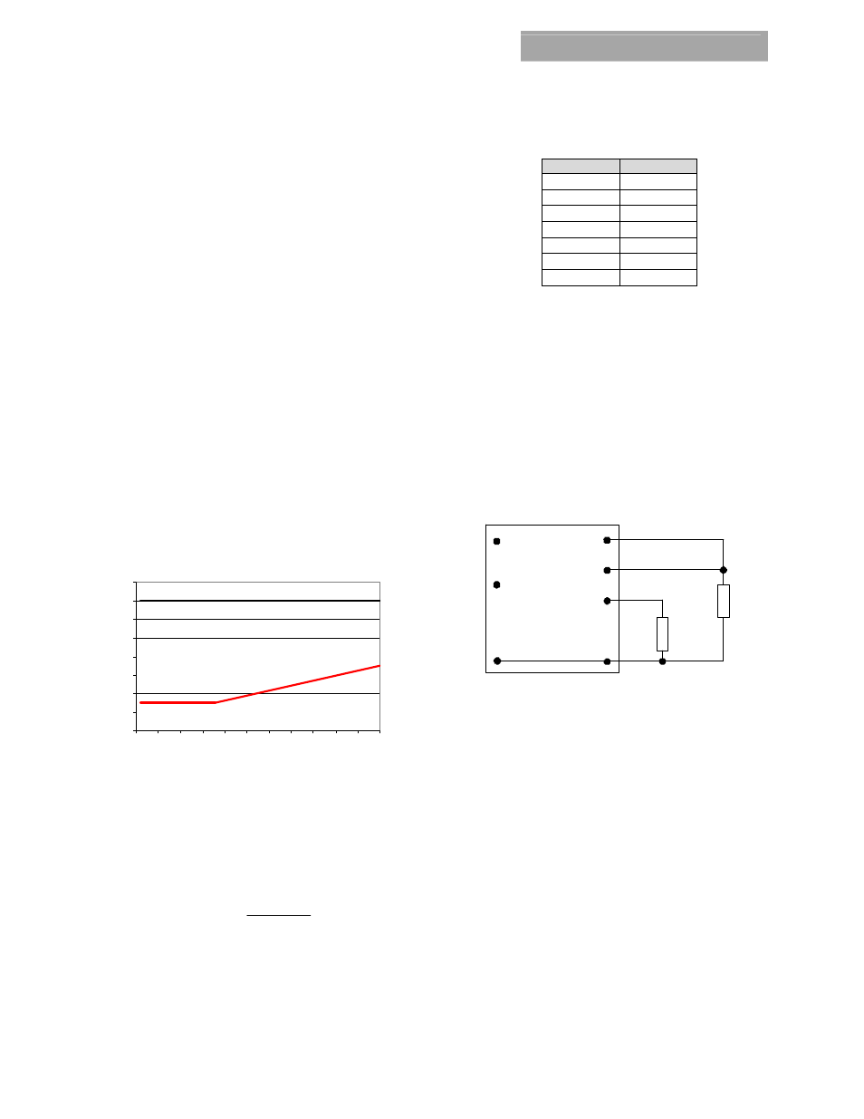
Certain restrictions apply on the output voltage set point
depending on the input voltage. These are shown in the Output
Voltage vs. Input Voltage Set Point Area plot in Fig. 55. The
Lower Limit curve shows that for output voltages of 2.4V and
higher, the input voltage needs to be larger than the minimum
of 3V.
0
2
4
6
8
10
12
14
16
0.5
1
1.5
2
2.5
3
3.5
4
4.5
5
5.5
6
Output Voltage (V)
Input
Volt
ag
e
(v
)
Figure 55. Output Voltage vs. Input Voltage Set Point Area
plot showing limits where the output voltage can be set for
different input voltages.
Without an external resistor between Trim and GND pins, the
output of the module will be 0.6Vdc. To calculate the value of
the trim resistor, Rtrim for a desired output voltage, use the
following equation:
(
)
Ω
−
=
k
Vo
Rtrim
6
.
0
0
.
6
Rtrim is the external resistor in kΩ
Vo is the desired output voltage.
Table 1 provides Rtrim values required for some common output
voltages.
Table 1
V
O, set
(V)
Rtrim (KΩ)
1.0 15
1.2 10
1.5 6.67
1.8 5
2.5 3.16
3.3 2.22
5.0 1.36
By using a ±0.5% tolerance trim resistor with a TC of
±100ppm, a set point tolerance of ±1.5% can be
achieved as specified in the electrical specification.
Remote Sense
The 12V PicoTLynx
TM
2A power modules have a Remote
Sense feature to minimize the effects of distribution
losses by regulating the voltage at the SENSE pin. The
voltage between the SENSE pin and VOUT pin must not
exceed 0.5V. Note that the output voltage of the module
cannot exceed the specified maximum value. This
includes the voltage drop between the SENSE and Vout
pins. When the Remote Sense feature is not being used,
connect the SENSE pin to the VOUT pin.
V
O
(+)
TRIM
GND
R
trim
LOAD
V
IN
(+)
ON/OFF
SENSE
Figure 56. Circuit configuration for programming
output voltage using an external resistor.
Voltage Margining
Output voltage margining can be implemented in the
12V PicoTLynx
TM
2A modules by connecting a resistor,
R
margin-up
, from the Trim pin to the ground pin for
margining-up the output voltage and by connecting a
resistor, R
margin-down
, from the Trim pin to output pin for
margining-down. Figure 10 shows the circuit
configuration for output voltage margining. The POL
Programming Tool, available at
www.lineagepower.com
under the Design Tools section, also calculates the values
of R
margin-up
and R
margin-down
for a specific output voltage
and % margin. Please consult your local GE Critical
Power technical representative for additional details.