GE Industrial Solutions Neutral Rogowski Current Transformer (CT) User Manual
Page 9
8
Neutral Assemblies Manual
DEH-41531 02/12
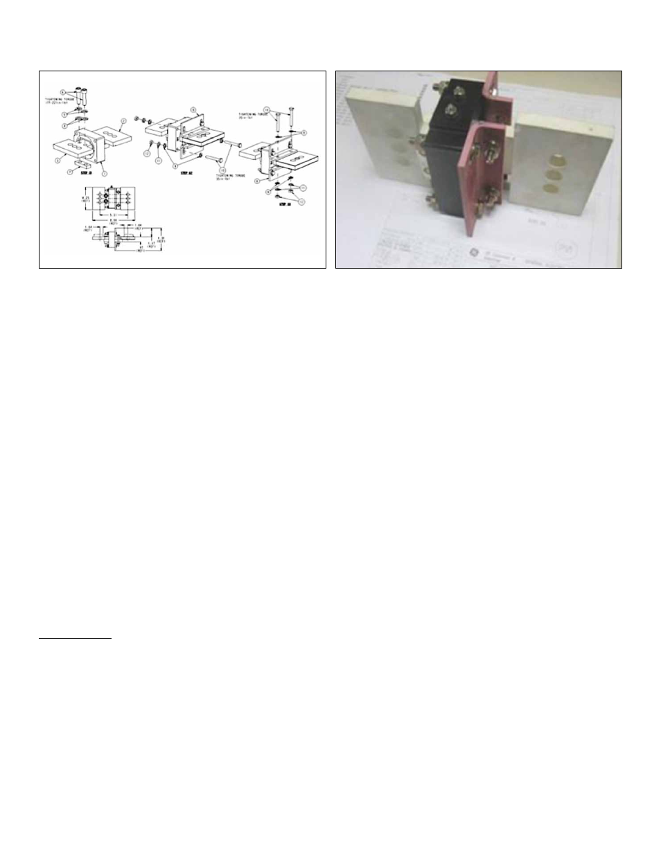
Figure 9. Neutral Bus Rogowski ASM 10108266
Figure 10. Neutral Bus Rogowski ASM 10108266 Photo
Neutral CT assembly in Cable/Bus Compartment
1. Ensure that the LVS has been de-energized and the breaker in the compartment being retrofit are switched
off and removed from the LVS.
2. Open the door on the rear of the compartment to gain access the Cable Bus compartment of the LVS.
3. The existing neutral CT assemblies are usually mounted vertically on two copper bus bars placed horizontally.
4. Disconnect the wires that are attached to the existing CT assemblies and place them such that they do not
interfere with the replacement of the CT assemblies.
5. Unfasten and remove the bolts that hold the neutral disconnect assemblies to the horizontal bus bars.
Keep the hardware in a secure location for reassembly.
6. Care should be taken while handling the CT assemblies such that they do not fall down or damage other
components within the LVS.
7. Replace the old CT assembly by the new Rogowski assembly on the horizontal bus bars and fasten it using
the hardware previously removed.
8. Connect the wires back to the Rogowski CT assembly leads. In case of damaged wire, the same must be
replaced with new ones as already mentioned.
9. Check for continuity from the CT leads to the plungers located on the neutral-disconnect assemblies in the
LVS compartment.
10. Verify that the new Rogowski assembly is installed and ready for use.
Tools required: Wrenches, Wire stripper, wire cutter, continuity tester