GE Industrial Solutions Neutral Rogowski Current Transformer (CT) User Manual
Page 6
5
Neutral Assemblies Manual
DEH-41531 02/12
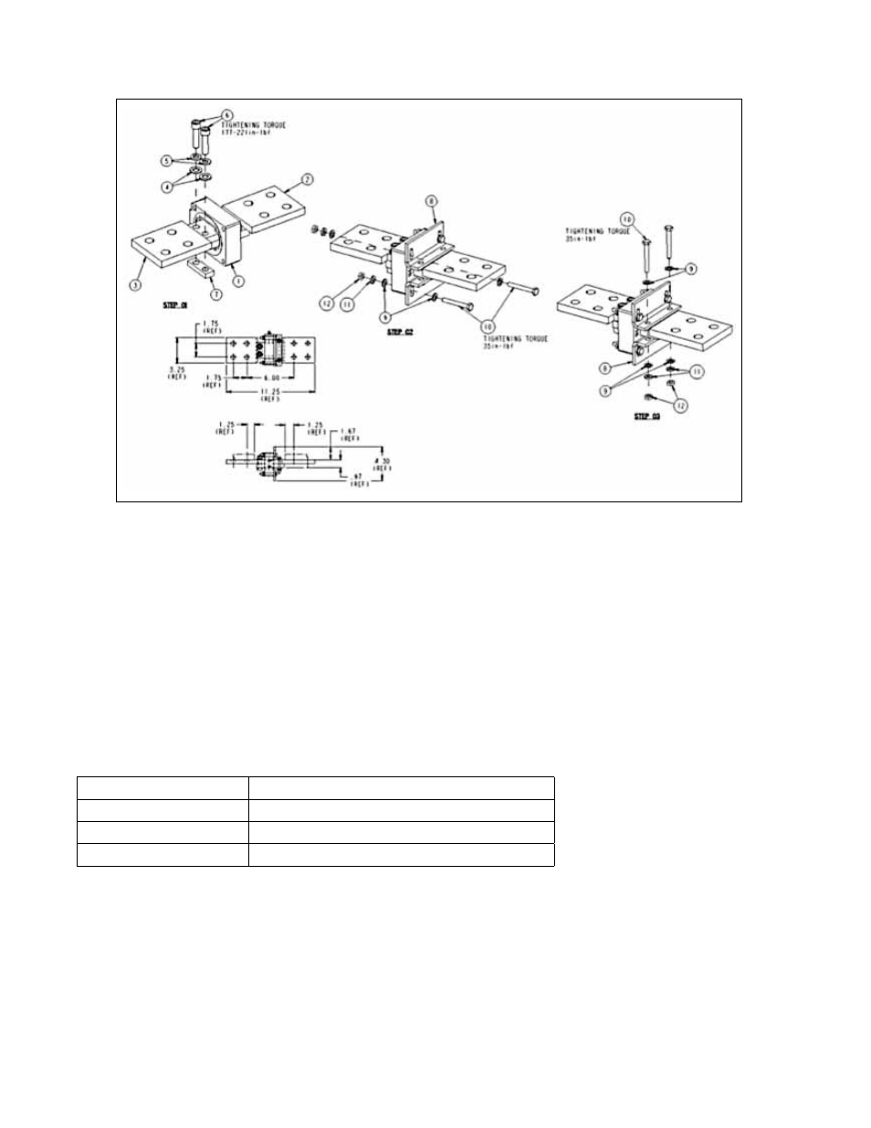
Figure 3. AKD-5—AK50 Neutral Bus Rogowski ASM 10108216
Table 1. Frame Ratings and Sensor Areas
AKD-5—Neutral Sensor Packaging
• The Neutral Sensor is constructed using a phase sensor encapsulated appropriately to meet insulation
and durability requirements.
• Lead wires are UL-recognized type 18AWG or larger, rated at 600V.
• Lead wires are 6 feet in length, minimum.
• Lead wires are colored white and black.
• The white wire is connected to the “positive” polarity termination.
• The black wire is connected to the “negative” polarity termination.
• Sensor window cross section conforms to criteria as found in the table below (
Table 1
):
Frame & Rating
Sensor Window minimum area (in
2
)
Frame 1 / 2000A
2.0
Frame 2 / 3200A
3.2
Frame 3 / 6400A
6.4
The Frame 3 neutral sensor is implemented as two separate sensors, similarly to the phase sensors in the circuit
breaker. Frame 3 neutral bus assemblies provide two independent parallel conductors in the neutral bus such
that the neutral current is divided between the two sensors.
A special neutral bus section is provided within the switchgear to accommodate the specific form factor of each
Rogowski—this is not the design responsibility of the Rogowski vendor.
• Encapsulation materials are UL recognized and suitable for operation at 130C.
• Neutral sensors of a given rating match all characteristics of the phase sensors.