GE Industrial Solutions Neutral Rogowski Current Transformer (CT) User Manual
Page 4
3
Neutral Assemblies Manual
DEH-41531 02/12
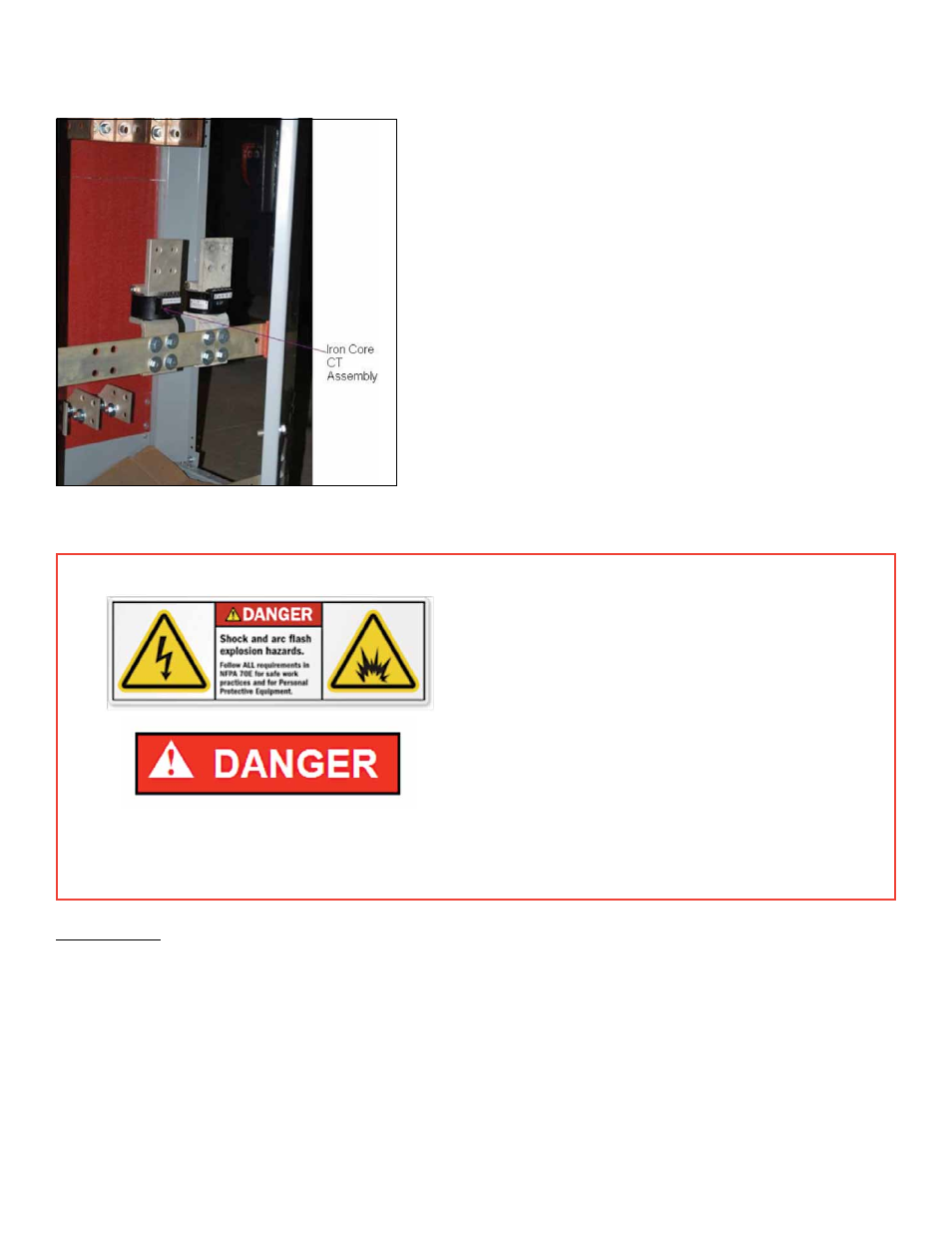
Figure 1. Neutral—AK25/50 Iron Core
Current Transformer Assembly
• Turn off all power to switchgear. Tagout
and lockout main source, up-stream or
main breaker.
• Failure to comply with these instructions
will result in death or serious injury from
severe burns caused by arc flashing that
has exceedingly high temperatures.
• Always wear personal protection equipment
according to OSHA standards and appropriate
to the severity of potential burns.
• Ensure only qualified personnel install, operate, service, and maintain all electrical equipment.
Tools required: Wrenches, Wire stripper, wire cutter, continuity tester.
1. Ensure that the LVS has been de-energized and the breaker in the compartment, being retrofitted, are
switched off and removed from the LVS.
2. Open the door at the rear of the compartment to access the cable/bus compartment of the LVS.
3. Note that the existing neutral CT assemblies are usually mounted vertically on two copper bus bars
placed horizontally.
4. Make a note of the neutral disconnect assembly orientation and the polarity of the wire connections.
This is needed so that the same orientation is maintained when the new CT assembly is installed.
Neutral CT in Cable/Bus Compartment