Test configurations, Design considerations, Input filtering – GE Industrial Solutions EQW006 Series User Manual
Page 7
Data Sheet
July 27, 2011
EQW006 Series, Eight Brick Power Modules: DC-DC Converter
36 – 75Vdc Input; 12Vdc Output; 6A Output Current
LINEAGE
POWER
7
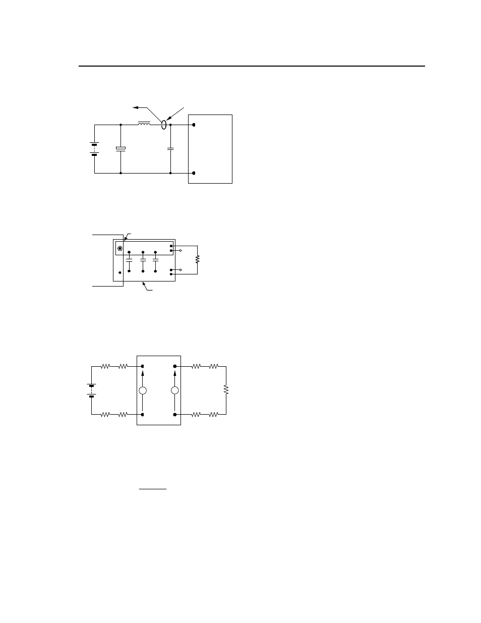
Test Configurations
TO OSCILLOSCOPE
CURRENT PROBE
L
TEST
12μH
BA
T
T
E
R
Y
C
S
220μF
E.S.R.<0.1
@ 20°C 100kHz
33μF
Vin+
Vin-
NOTE: Measure input reflected ripple current with a simulated
source inductance (L
TEST
) of 12μH. Capacitor C
S
offsets
possible battery impedance. Measure current as shown
above.
Figure 7. Input Reflected Ripple Current Test
Setup.
NOTE: All voltage measurements to be taken at the module
terminals, as shown above. If sockets are used then
Kelvin connections are required at the module terminals
to avoid measurement errors due to socket contact
resistance.
V
O
(+)
V
O
(
–
)
0.01uF
RESISTIVE
LOAD
SCOPE
COPPER STRIP
GROUND PLANE
10uF
0.1uF
Figure 8. Output Ripple and Noise Test Setup.
Vout+
Vout-
Vin+
Vin-
R
LOAD
R
contact
R
distribution
R
contact
R
distribution
R
contact
R
contact
R
distribution
R
distribution
V
IN
V
O
NOTE: All voltage measurements to be taken at the module
terminals, as shown above. If sockets are used then
Kelvin connections are required at the module terminals
to avoid measurement errors due to socket contact
resistance.
Figure 9. Output Voltage and Efficiency Test
Setup.
=
V
O
. I
O
V
IN
. I
IN
x
100
%
Efficiency
Design Considerations
Input Filtering
The power module should be connected to a low
ac-impedance source. Highly inductive source
impedance can affect the stability of the power
module. For the test configuration in Figure 7 a 33μF
electrolytic capacitor (ESR<0.7
at 100kHz),
mounted close to the power module helps ensure the
stability of the unit. Consult the factory for further
application guidelines.