GE Industrial Solutions Austin MegaLynx SMT User Manual
Page 18
Data Sheet
September 10, 2013
Austin MegaLynx
TM
SMT: Non-Isolated DC-DC Power Modules:
4.5 – 5.5Vdc input; 0.8 to 3.63Vdc Output; 30A output current
6.0 – 14Vdc Input; 0.8Vdc to 3.63Vdc Output; 20/30A output
LINEAGE
POWER
18
Vo is the desired output voltage
By using a ±0.5% tolerance trim resistor with a TC
of ±100ppm, a set point tolerance of ±1.5% can be
achieved as specified in the electrical specification.
Table 1 provides Rtrim values required for some
common output voltages. The POL Programming
Tool, available at
www.lineagepower.com
under the
Design Tools section, helps determine the required
external trim resistor needed for a specific output
voltage.
V
O
(+)
TRIM
GND
LOAD
V
IN
(+)
ON/OFF
Rtrim
Figure 52. Circuit configuration to program
output voltage using an external resistor.
Table 1
V
O, set
(V)
Rtrim (KΩ)
0.8 Open
1.0 5.900
1.2 2.900
1.5 1.614
1.8 1.100
2.5 0.606
3.3 0.380
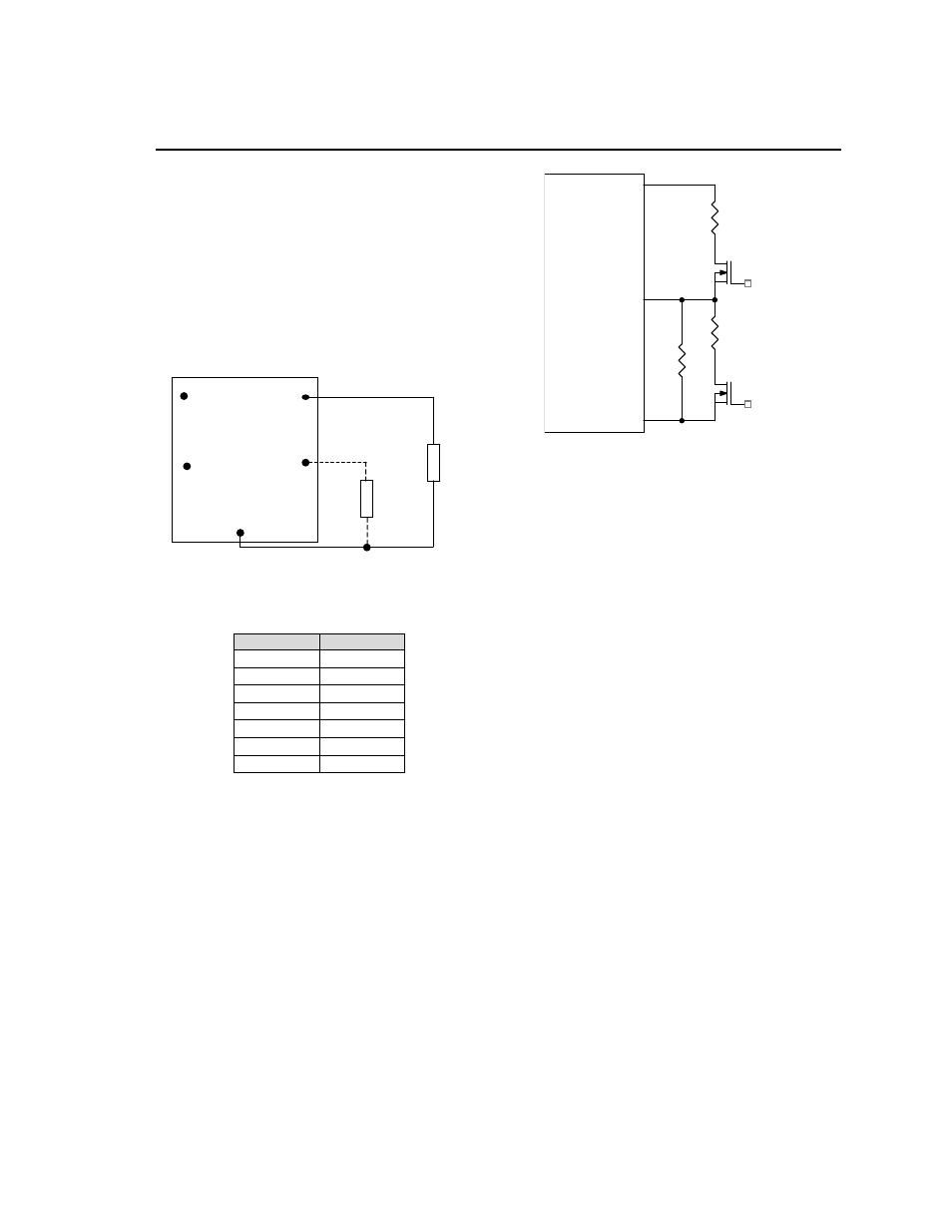
Voltage Margining
Output voltage margining can be implemented in
the Austin MegaLynx
TM
modules by connecting a
resistor, R
margin-up
, from the Trim pin to the ground
pin for margining-up the output voltage and by
connecting a resistor, R
margin-down
, from the Trim pin
to output pin for margining-down. Figure 53 shows
the circuit configuration for output voltage
margining. The POL Programming Tool, available
at
www.lineagepower.com
under the Design Tools
section, also calculates the values of R
margin-up
and
R
margin-down
for a specific output voltage and %
margin. Please consult your local Lineage Power
technical representative for additional details.
Figure 53. Circuit Configuration for margining
Output voltage.
Voltage Sequencing
The Austin MegaLynx
TM
series of modules include a
sequencing feature that enables users to implement
various types of output voltage sequencing in their
applications. This is accomplished via an additional
sequencing pin. When not using the sequencing
feature, either leave the SEQ pin unconnected or
tied to V
IN
.
For proper voltage sequencing, first, input voltage is
applied to the module. The On/Off pin of the
module is or tied to GND so that the module is ON
by default. After applying input voltage to the
module, a delay of 10msec minimum is required
before applying voltage on the SEQ pin. During this
delay time, the SEQ pin should be kept at a voltage
of 50mV (± 20 mV). After the 10msec delay, the
voltage applied to the SEQ pin is allowed to vary
and the output voltage of the module will track this
voltage on a one-to-one volt basis until the output
reaches the set-point voltage. To initiate
simultaneous shutdown of the modules, the SEQ
pin voltage is lowered in a controlled manner. The
output voltages of the modules track the sequence
pin voltage when it falls below their set-point
voltages. A valid input voltage must be maintained
until the tracking and output voltages reach zero to
ensure a controlled shutdown of the modules. For a
more detailed description of sequencing, please
refer to Application Note AN04-008 titled
“Guidelines for Sequencing of Multiple
Modules”.
When using the EZ-SEQUENCE
TM
feature to
control start-up of the module, pre-bias immunity
Vo
Austin Lynx or
Lynx II Series
GND
Trim
Q1
Rtrim
Rmargin-up
Q2
Rmargin-down