Input; 15.0v, Output, Thermal considerations – GE Industrial Solutions ESTW004A2C Series User Manual
Page 9: Continued)
Data Sheet
August 30, 2011
ESTW004A2C Series DC-DC Converter Power Modules
36–75V
dc
Input; 15.0V
dc
/4.2A
dc
Output
LINEAGE
POWER
9
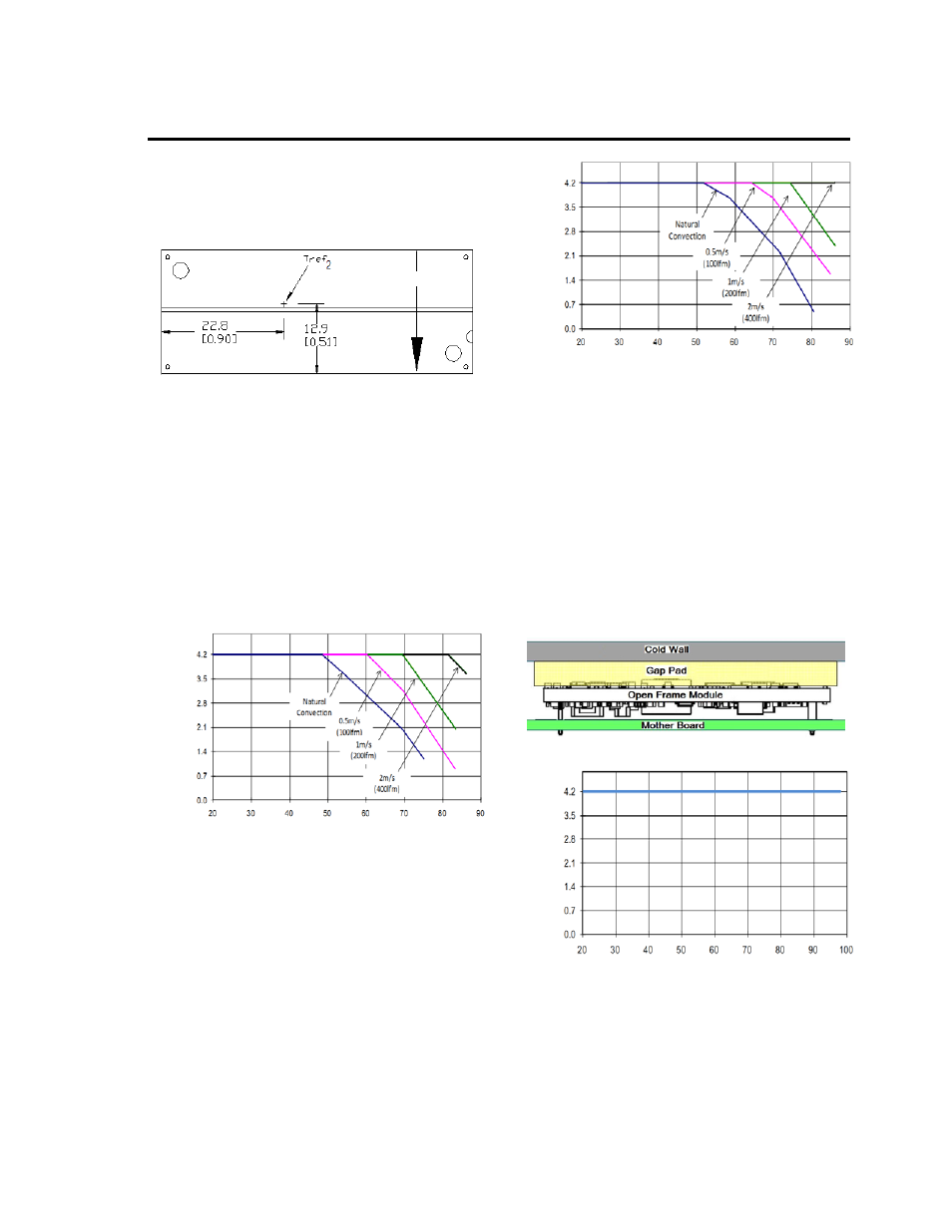
Thermal Considerations
(continued)
The thermal reference point, T
ref2
,
used in the
specifications for modules with heatplate is shown in
Figure 13. For reliable operation this temperature
should not exceed 104
o
C.
Figure 13. T
ref
Temperature Measurement
Location for Module with Heatplate.
Heat Transfer via Convection
Increased airflow over the module enhances the heat
transfer via convection. Derating curves showing the
maximum output current that can be delivered by
each module versus local ambient temperature (T
A
)
for natural convection and up to 2m/s (400 ft./min)
forced airflow are shown in Figure 14.
Please refer to the Application Note “Thermal
Characterization Process For Open-Frame Board-
Mounted Power Modules” for a detailed discussion of
thermal aspects including maximum device
temperatures.
OUT
P
UT C
URR
EN
T
, I
O
(A
)
AMBIENT TEMEPERATURE, T
A
(
o
C
)
Figure 14. Output Current Derating for the Open
Frame Module; Airflow in the Transverse Direction
from V
OUT
(+) to V
OUT
(-); V
IN
=48V.
O
U
TP
UT
CU
RRE
NT
, I
O
(A
)
AMBIENT TEMEPERATURE, T
A
(
o
C
)
Figure 15. Output Current Derating for the Module
with Heatplate; Airflow in the Transverse Direction
from V
OUT
(+) to V
OUT
(-); V
IN
=48V.
Heat Transfer via Conduction
The module can also be used in a sealed
environment with cooling via conduction from the
module’s top surface through a gap pad material to a
cold wall, as shown in Figure 16. This capability is
achieved by insuring the top side component skyline
profile achieves no more than 1mm height difference
between the tallest and the shortest power train part
that benefits from contact with the gap pad material.
The output current derating versus cold wall
temperature, when using a gap pad such as Bergquist
GP2500S20, is shown in Figure 17.
Figure 16. Cold Wall Mounting
O
U
TP
UT
CU
RRE
NT
, I
O
(A
)
COLDPLATE TEMEPERATURE, T
C
(
o
C)
Figure 17. Derated Output Current versus Cold
Wall Temperature with local ambient temperature
around module at 85C; V
IN
=48V.
AIRFLOW