Input; 15.0v, Output, Surface mount information – GE Industrial Solutions ESTW004A2C Series User Manual
Page 11: Through-hole lead-free soldering information, Continued), Pb-free reflow profile, Msl rating, Storage and handling, Post solder cleaning and drying considerations
Data Sheet
August 30, 2011
ESTW004A2C Series DC-DC Converter Power Modules
36–75V
dc
Input; 15.0V
dc
/4.2A
dc
Output
LINEAGE
POWER
11
Surface Mount Information
(continued)
RE
F
LO
W
T
E
MP
(
C)
REFLOW TIME (S)
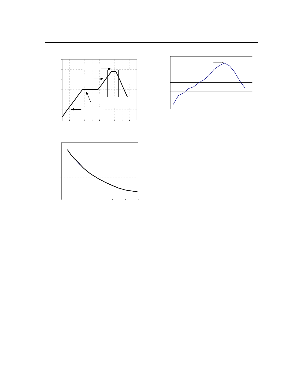
Figure 20. Reflow Profile for Tin/Lead (Sn/Pb)
process
M
A
X
TEM
P
SOLDER (
C)
Figure 21. Time Limit Curve Above 205
o
C for
Tin/Lead (Sn/Pb) process
Pb-free Reflow Profile
Power Systems will comply with J-STD-020 Rev. C
(Moisture/Reflow Sensitivity Classification for
Nonhermetic Solid State Surface Mount Devices) for
both Pb-free solder profiles and MSL classification
procedures. This standard provides a recommended
forced-air-convection reflow profile based on the
volume and thickness of the package (table 4-2). The
suggested Pb-free solder paste is Sn/Ag/Cu (SAC).
The recommended linear reflow profile using
MSL Rating
The ESTW004A2C modules have a MSL rating of 2a.
Storage and Handling
The recommended storage environment and handling
procedures for moisture-sensitive surface mount
packages is detailed in J-STD-033 Rev. A (Handling,
Packing, Shipping and Use of Moisture/Reflow
Sensitive Surface Mount Devices). Moisture barrier
bags (MBB) with desiccant are required for MSL
Sn/Ag/Cu solder is shown in Figure 23.
Figure 22. Recommended linear reflow profile
using Sn/Ag/Cu solder.
ratings of 2 or greater. These sealed packages
should not be broken until time of use. Once the
original package is broken, the floor life of the product
at conditions of
30°C and 60% relative humidity
varies according to the MSL rating (see J-STD-033A).
The shelf life for dry packed SMT packages will be a
minimum of 12 months from the bag seal date, when
stored at the following conditions: < 40° C, < 90%
relative humidity.
Post Solder Cleaning and Drying
Considerations
Post solder cleaning is usually the final circuit-board
assembly process prior to electrical board testing. The
result of inadequate cleaning and drying can affect
both the reliability of a power module and the
testability of the finished circuit-board assembly. For
guidance on appropriate soldering, cleaning and
drying procedures, refer to Lineage Power Board
Mounted Power Modules: Soldering and Cleaning
Application Note (AN04-001).
Through-Hole Lead-Free Soldering
Information
The RoHS-compliant through-hole products use the
SAC (Sn/Ag/Cu) Pb-free solder and RoHS-compliant
components. They are designed to be processed
through single or dual wave soldering machines. The
pins have a RoHS-compliant finish that is compatible
with both Pb and Pb-free wave soldering processes.
A maximum preheat rate of 3
C/s is suggested. The
wave preheat process should be such that the
temperature of the power module board is kept below
210
C. For Pb solder, the recommended pot
temperature is 260
C, while the Pb-free solder pot is
270
C max. Not all RoHS-compliant through-hole
products can be processed with paste-through-hole
Pb or Pb-free reflow process. If additional information
is needed, please consult with your Lineage Power
representative for more details.
0
50
100
150
200
250
300
Preheat zone
max 4
o
Cs
-1
Soak zo ne
30-240s
Heat zone
max 4
o
Cs
-1
Peak Temp 235
o
C
Coo ling
zone
1-4
o
Cs
-1
T
lim
above
205
o
C
200
205
210
215
220
225
230
235
240
0
10
20
30
40
50
60
Pe r J-STD-020 Rev. C
0
50
100
150
200
250
300
Reflow Time (Seconds)
R
efl
o
w
Te
m
p
(°
C
)
Heating Zone
1°C/Second
Peak Temp 260°C
* Min. Time Above 235°C
15 Se conds
*Time Above 217°C
60 Seconds
Cooling
Zone