4 of 8, Communication signals: j1 connector, Communication signals: j2 connector – GE Industrial Solutions J85480S1, L20 – L29 Compact Power Line Shelves User Manual
Page 4: Signal connector part numbers
4 of 8
COMPACT POWER LINE SHELVES – MODEL J85480S1
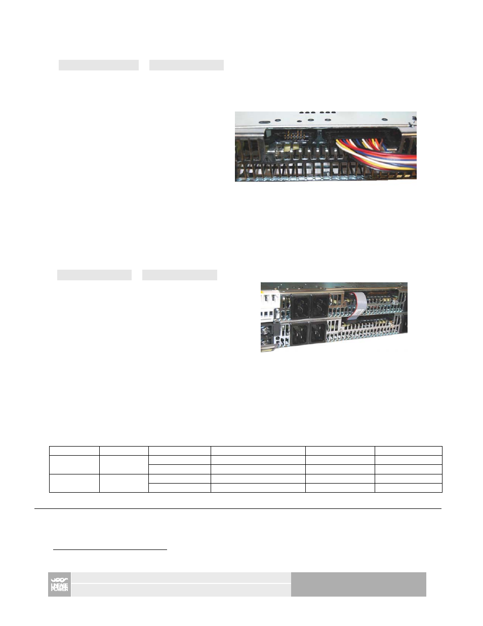
Communication Signals: J1 Connector
Pin out
Control Interface cable (part # CC848854034)
Pin
Signal
Pin
Signal
1 POWER_CAP_1 16 SDA_1
2 POWER_CAP_2 17 Fault
3 POWER_CAP_3 18 Alert#_0
4
POWER_CAP_4
19
Enable side B
5 MOD_PRES_1
20 Logic_GRD
6
MOD_PRES_2
21
Enable Side A
7 MOD_PRES_3
22 Logic_GRD
8 MOD_PRES_4
23 Alert#_1
9 PFW_1
24 5VA
10 PFW_2
25 OTW
11 PFW_3
26 Reset
12
PFW_4
27
Iso. barrier n/c
13
SCL_0
28
Iso. barrier n/c
14 SCL_1
29 Shelf_Addr_B
15 SDA_0
30 Shelf_Addr_A
Communication Signals: J2 Connector
Pin out
Shelf-to-shelf cable connection (part # CC848848952)
Pin
Signal
Pin
Signal
1 SCL_0
8 Alert#_1
2 SCL_1
9
Isolation
n/c
3 SDA_0
10
Isolation
n/c
4
SDA_1
11
Ishare - B
5
Alert#_0
12
Ishare - A
6
5VA
13
8V_INT - B
7
Logic_GRD
14
8V_INT - A
Notes:
Shelf addressing, 8V_INT, and current share are referenced to the most negative power output Vout(-) of the shelf. For
paralleled shelves the Vout(-) terminations must be tied together in order to ensure proper operation of these functions. Modules could get
damaged if this connection is not made.
For address A2=0, leave Shelf_Addr_x N/C. For A2=1, connect Shelf_Addr_x to Vout(-). For all other signals refer to rectifier data sheet.
Signal connector part numbers
( AMP – as specified or equivalent)
Connector
Positions
On shelf
Ribbon cable
Individual wires
Crimping tool
J1 30
5102159-7
1658621-7 header
102387-7 header
102320-1 latch
1-499252-2 retainer
6-87756-8 pin
2
91517-1
J2
14
5102159-2
1658621-2 header
102387-2 header
102320-1 latch
499252-9 retainer
6-87756-8 pin
91517-1
2
For 22 – 26ga wires