GE Industrial Solutions EntelliGuard E Circuit Breaker User Manual
Page 21
©2012 General Electric All Rights Reserved
21
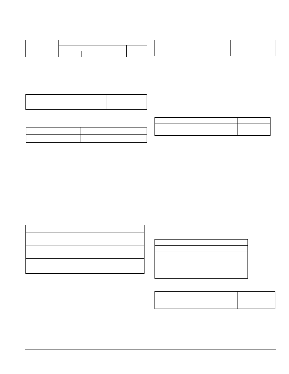
Table 6.4. Remote Operation Coil Combination
Combination
Coil Position on Fascia (from left)
1 2
3
1
NI SET
NI RESET
CC
ST
Auxiliary Switches
Auxiliary switches indicate breaker main contact position.
They change their state in the same time sequence as the
breaker main contacts. See Table 6.6 for rating.
Table 6.5. Auxiliary Switches
Contact Configuration Cat.
No.
Power rated (3NO+3NC)
GAUX3R
Table 6.6. Auxiliary Switch Ratings and Secondary
Disconnect Points
Contact Configuration
Power Rated Cat. No.
Power rated(3NO+3NC)
A14 - A25
GAUX3R
Circuit Breaker - Key Interlock Facility
This option provides factory-installed interlocking devices for
installation between separate circuit breakers (baseplates and
mechanism). This safeguard ensures that a circuit breaker
cannot be closed unless the dedicated key has been inserted
and secured within the lock. Circuit breakers accept ready-to-fit
interlocking device kits such as Kirk for installation between
related, separate circuit breakers (Table 6.7).
NOTE: Locks and keys are not supplied by GE. Please order
separately from your local supplier.
Table 6.7. Key Interlocks and Door Interlocks
Description Catalog
Number
Baseplate and mechanism for Kirk Key
locks (breaker mounted)
GBKRKR
Mechanism for Kirk key cassette interlock
(cassette mounted)
GCKRKR
Door interlock (left side)
GLHD
Door interlock (right side)
GRHD
Carriage Position Switch (TOC)
Available as an option for mounting within the base of the
cassette/substructure, the carriage position switch provides
changeover contacts for electrical indication of the circuit
breaker status: CONNECTED & TEST. This option is in addition
to the mechanical indicators, which are fitted as standard.
When installed, the carriage switch is IP2X protected and
includes wiring to a terminal block located on the left side of
the cassette (Table 6.8).
Table 6.8. Carriage Position Switches
Switch Configuration
Catalog Number
1 NO/NC switch per position
GCPS4R
Bell Alarm with Lockout
The bell alarm provides remote indication that the circuit
breaker has opened because of an electrical fault. The
Lockout feature is integral to the trip unit. When a Bell Alarm
is supplied with the breaker, the trip unit dial is set and
locked to the manual position. In order to re-close the
breaker, the Lockout button must be pushed in/reset on the
trip unit 1-Form C contact (Table 6.9).
Table 6.9. Bell Alarm Switches
Switch Configuration
Cat. No.
One single pole, double throw switch
(1-Form C contact)
GBAT1R
Charging Spring Status Indicator
Factory-installed on the motor, this auxiliary switch indicates
that the circuit breaker is charged and is standard with the
spring-charging motor.
Secondary Disconnects (Factory-installed/Field
Installable)
Inputs and outputs to the circuit breaker are wired through
secondary disconnects located on the top of the breaker.
The plug-style secondary disconnects engage mating
disconnects in the breaker cubicle when the breaker is in the
TEST or CONNECT position. Up to 39 points are available so
that all breaker accessories can be wired to dedicated
disconnect points. See Table 6.10 for block location and
Table 6.11 for secondary disconnect parts.
Table 6.10. Block Location
Top Disconnect
Block B
Block A
circuit breaker/cradle
viewed from the front
Table 6.11. Secondary Disconnect Parts
Breaker Type
Mounting
Number of
Poles
Cat. No.
Drawout
Top
39 pole set
GSDWSR
Set contains both the male and female sides of the secondary
disconnect.
Drawout kits include the metal bracket for connections to the cassette.