Danger, Warning, Caution – GE Industrial Solutions EntelliGuard E Circuit Breaker User Manual
Page 18: Notice
EntelliGuard® E Circuit Breaker
DEH-41526
18
©2012 General Electric All Rights Reserved
SECTION 5 – LOCKS AND INTERLOCKS
DANGER
ELECTROCUTION
Ensure the circuit breaker has been tripped, indicating
OFF, and the main springs are fully discharged before
installing locks and interlocks.
Failure to comply with these instructions will result
in death or serious injury.
WARNING
IMPROPER INSTALLATION, OPERATION AND
MAINTENANCE
Ensure only qualified personnel install, operate,
service and maintain all electrical equipment.
Failure to comply with these instructions could
result in death or serious injury.
WARNING
PERSONAL INJURY
Avoid risk of injury from moving parts while
handling the circuit breaker.
Failure to comply with these instructions could
result in death or serious injury.
CAUTION
PRODUCT DAMAGE
Ensure the circuit breaker and its accessories are
always used within their designated ratings.
Failure to comply with these instructions may result
in product damage.
GENERAL INFORMATION
NOTICE
Ensure all padlocks are scissor compatible.
A variety of locks and interlock accessories are available.
The operation of most of these accessories is described in
this section.
CIRCUIT BREAKER FRONT PANEL LOCKING
Padlock or Scissor Lock for Breaker Trip Free Condition
1. While pressing the OFF pushbutton, pull out the
padlock lever.
2. Ensure padlock shaft diameter is 3 mm to 9.5 mm.
3. Insert padlock hasp (Fig. 5.1).
Figure 5.1. Padlock for Breaker Trip Free Condition
DRAWOUT CASSETTE FRONT PANEL LOCKING
Security Locking
This function locks the entry of the racking handle in the
crank insertion hole of the cassette front panel when the
padlock is installed when circuit breaker in the
DISCONNECTED/ CONNECTED position. Up to three
padlocks (shaft diameter of 3 mm to 9.5 mm) may be
installed for additional security (Fig. 5.2).
Figure 5.2. Circuit Breaker Security Padlocking Location
A Security Locking Bar
1. Ensure the position indicator shows the
DISCONNECTED/CONNECTED position.
2. Remove the racking handle from the operating
position.
3. Pull the locking bar until the locking eye is exposed
and hold while inserting the padlock shaft (Fig. 5.3).
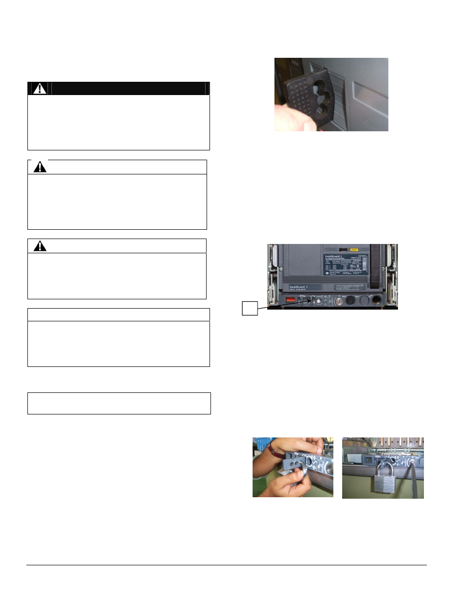
Figure 5.3. Padlock Insertion and Lock-Out on the
Security Locking Bar
Isolation Shutters Locking (If Installed)
This function locks the operation of the safety shutters
when the padlock is installed on the security locking
A