GE Industrial Solutions EntelliGuard E Circuit Breaker User Manual
Page 10
EntelliGuard® E Circuit Breaker
DEH-41526
10
©2012 General Electric All Rights Reserved
The trip unit measures current and protects the breaker by
providing instantaneous over current override protection.
The fascia has interface buttons and features for safety
locks.
The cassette consists of a mechanism which enables the
circuit breaker to be racked in and out, and houses the
interlocks.
The front panel on the cassette has three markings which
indicate whether the breaker is in the CONNECTED, TEST or
DISCONNECTED position.
Drawout Circuit Breaker Installation into the Cassette
1. Pull the lifting handles on both side walls of the circuit
breaker.
2. Attach the lifting bar between the two holes of the lifting
eyes as shown in Fig. 3.3.
Figure 3.3. Circuit Breaker Lifting
3. Remove any padlocks and keep the key in place for key
locks if applied from the racking panel of the cassette.
4. Ensure the cassette position indicator shows
DISCONNECTED and the racking handle is disengaged.
5. Ensure the cassette racking cams on both side walls of
the cassette are in the completely racked out position
as shown in Fig. 3.4.
Figure 3.4. Racking Drive in the DISCONNECTED Position
6. Pull out the cassette rails fully.
7. Lower the circuit breaker gradually so that the rollers
drop over the rails. Ensure the grooves in all rollers
straddle the rails as shown in Fig. 3.5.
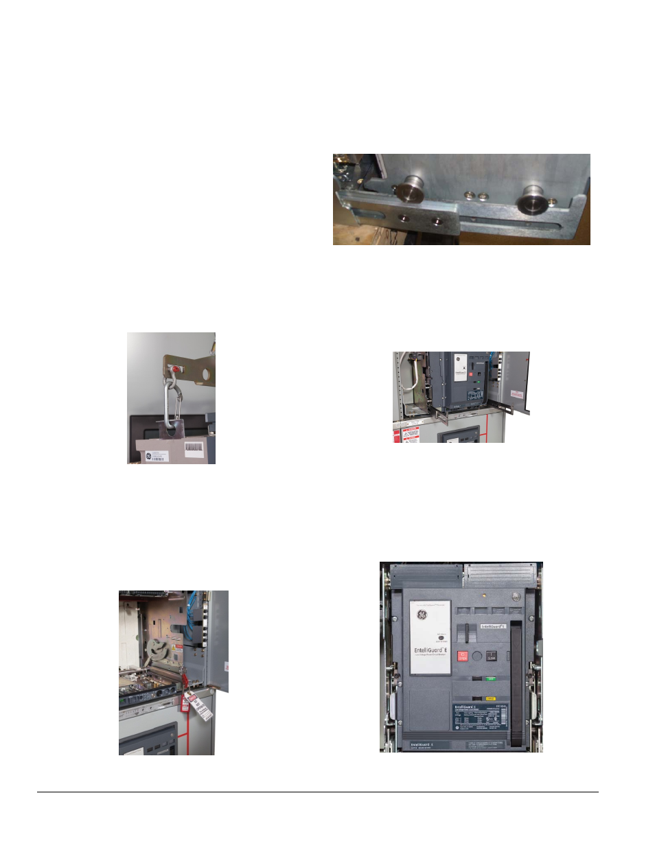
Figure 3.5. Circuit Breaker Rollers Straddled on the
Loading Rails
8.
Remove the lifting bar and push the circuit breaker into
the cassette until it reaches a positive stop (the racking
pins on the circuit breaker are engaged with the
racking cams of the cassette on both sides). The circuit
breaker is now in the DISCONNECTED position (Fig. 3.6).
Figure 3.6. Circuit Breaker in DISCONNECTED Position
9. Push back both the extended rails of the cassette to the
stowed position.
10. Close the circuit breaker cubicle door.
11. If the circuit breaker is CLOSED and the springs are
charged, press the OPEN button on the circuit breaker
fascia and ensure the circuit breaker contacts are open
(Fig. 3.7).
Figure 3.7. Setting the Circuit Breaker to OFF