Feature description – GE Industrial Solutions ESTW010A0A Series User Manual
Page 8
Data Sheet
November 29, 2011
ESTW010A0A Series Eighth-Brick Power Modules
36
–75Vdc Input; 5.0Vdc Output; 10A Output Current
LINEAGE
POWER
8
Feature Description
(continued)
If the unit is configured with the auto-restart option (4),
it will remain in the hiccup mode as long as the
overcurrent condition exists; it operates normally,
once the output current is brought back into its
specified range. The average output current during
hiccup is 10% I
O, max
.
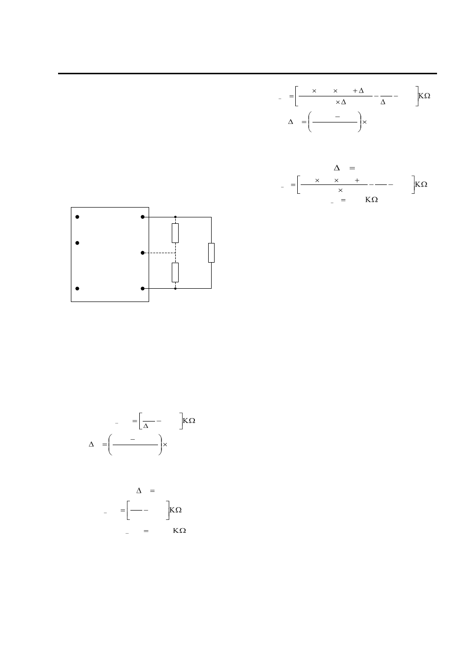
Output Voltage Programming
Trimming allows the output voltage set point to be
increased or decreased, this is accomplished by
connecting an external resistor between the TRIM pin
and either the V
O
(+) pin or the V
O
(-) pin.
V
O
(+)
V
O
TRIM
V
O
(-)
R
trim-down
LOAD
V
IN
(+)
ON/OFF
V
IN
(-)
R
trim-up
Figure 12. Circuit Configuration to Trim Output
Voltage.
Connecting an external resistor (R
trim-down
) between
the TRIM pin and the V
O
(-) (or Sense(-)) pin
decreases the output voltage set point. To maintain
set point accuracy, the trim resistor tolerance should
be ±1.0%.
The following equation determines the required
external resistor value to obtain a percentage output
voltage change of Δ%
22
.
10
%
511
down
trim
R
Where
100
%
,
,
set
o
desired
set
o
V
V
V
For example, to trim-down the output voltage of the
module by 8% to 11.04V, Rtrim-down is calculated as
follows:
8
%
22
.
10
8
511
down
trim
R
655
.
53
down
trim
R
Connecting an external resistor (R
trim-up
) between the
TRIM pin and the V
O
(+) (or Sense (+)) pin increases
the output voltage set point. The following equation
determines the required external resistor value to
obtain a percentage output voltage change of Δ%:
22
.
10
%
511
%
225
.
1
%)
100
(
11
.
5
, set
o
up
trim
V
R
Where
100
%
,
,
set
o
set
o
desired
V
V
V
For example, to trim-up the output voltage of the
module by 5% to 12.6V, R
trim-up
is calculated is as
follows:
5
%
22
.
10
5
511
5
225
.
1
)
5
100
(
0
.
12
11
.
5
up
trim
R
8
.
938
up
trim
R
The voltage between the V
O
(+) and V
O
(
–) terminals
must not exceed the minimum output overvoltage
protection value shown in the Feature Specifications
table. This limit includes any increase in voltage due
to remote-sense compensation and output voltage
set-point adjustment trim.
Although the output voltage can be increased by both
the remote sense and by the trim, the maximum
increase for the output voltage is not the sum of both.
The maximum increase is the larger of either the
remote sense or the trim. The amount of power
delivered by the module is defined as the voltage at
the output terminals multiplied by the output current.
When using remote sense and trim, the output voltage
of the module can be increased, which at the same
output current would increase the power output of the
module. Care should be taken to ensure that the
maximum output power of the module remains at or
below the maximum rated power (Maximum rated
power = V
O,set
x I
O,max
).