GE Industrial Solutions MicroVersaTrip Plus and MicroVersaTrip PM AK-25 and AKU-25 User Manual
Page 5
5
SECTION 2 INSTALLING THE
PROGRAMMABLE TRIP UNIT
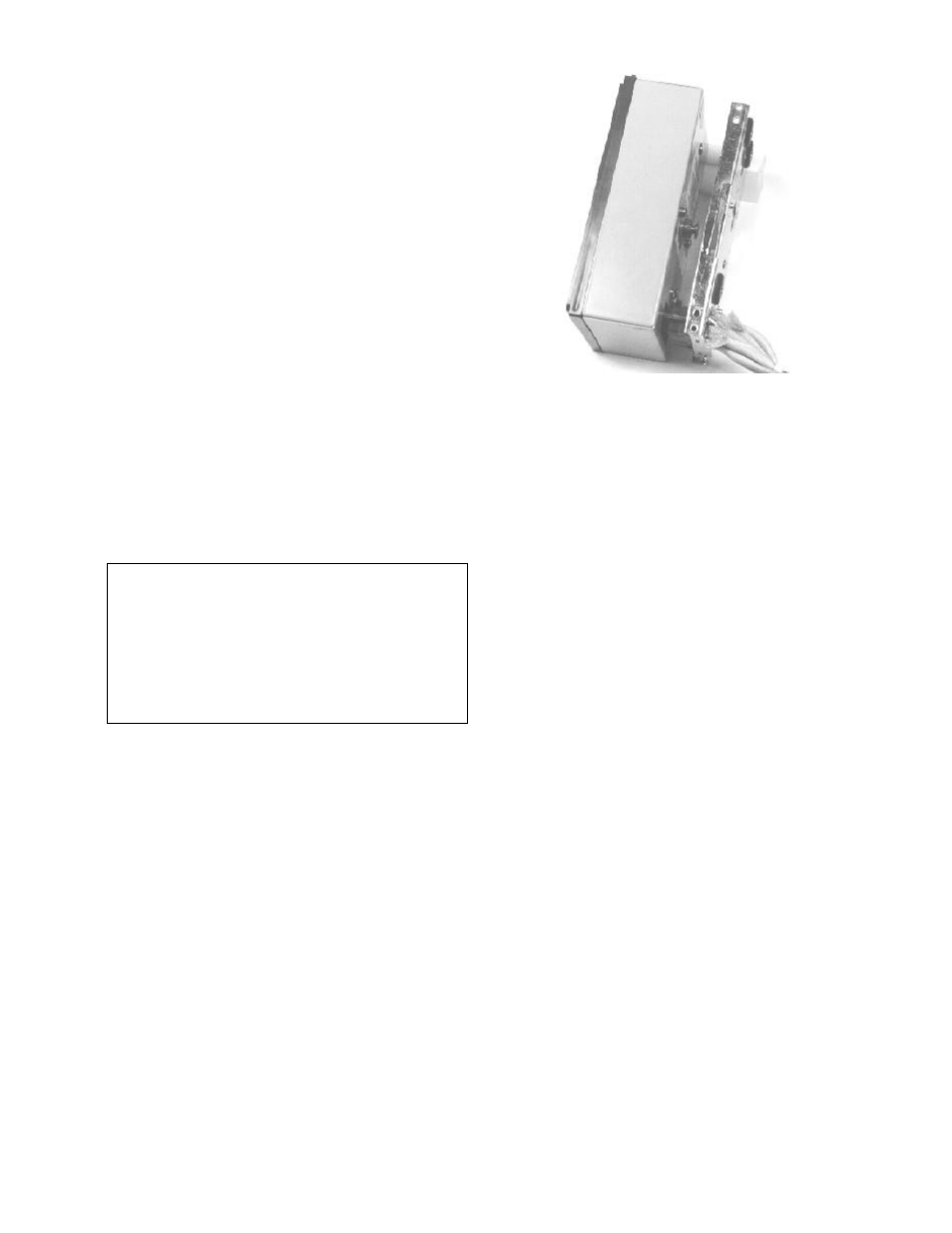
The programmer is attached to the programmer
mounting bracket. The guide pins in the bracket
mate with the holes on either side of the
programmer box. The guide pins provide the
necessary alignment for the connector
engagement. The locking lever engages with the
pin, which is assembled to the programmer unit,
and secures the programmer to the mounting
bracket.
To Install the Programmer:
Step 1.
Insert the guide pins into the holes and push on
the programmer. This will engage the connectors
and release the locking lever which will move
upwards (Fig. 2).
Step 2.
Verify that the locking lever actually engaged with
the pin on the rear of the programmer.
To remove the programmer, pull the locking lever
down, thus releasing the programmer pin. Then,
remove the programmer.
WARNING: BE SURE TO PERFORM THE
CONTINUITY TEST DETAILED IN STEP 1 OF
TESTING ON PAGE 6 PRIOR TO ENERGIZING
OR PRIMARY INJECTING THE CONVERTED
BREAKER. FAILURE TO DO SO MAY RESULT IN
DAMAGE TO THE PROGRAMMER UNIT, WIRE
HARNESS, 36-PIN PROGRAMMER CONNECTOR
AND CT’S. FAILURE TO ADHERE TO THESE
INSTRUCTIONS WILL VOID ALL WARRANTIES.
Fig. 2. Programmer Installation