GE Industrial Solutions MicroVersaTrip Plus and MicroVersaTrip PM AK-25 and AKU-25 User Manual
Page 3
3
SECTION 1 INSTALLING THE
WIRE HARNESS ASSEMBLY
Wire Harness Connector Assembly and
Installation
The wire harness includes a 36-pin programmer
connector, which must be assembled and installed
to the programmer bracket prior to the installation
of the programmer unit.
WARNING: THE ADAPTER BRACKET MUST BE
INSTALLED ONTO THE PROGRAMMER 36-PIN
CONNECTOR AND PROGRAMMER BRACKET AS
DETAILED BELOW. FAILURE TO DO SO WILL
RESULT IN HARNESS PLUG FAILURE AND THE
PROGRAMMER WILL NOT PROVIDE
PROTECTION. IF THE CONVERTED BREAKER IS
ENERGIZED OR PRIMARY INJECTED WITH THE
ADAPTER BRACKET NOT INSTALLED OR
INSTALLED IMPROPERLY, DAMAGE WILL
RESULT TO THE PROGRAMMER UNIT, WIRE
HARNESS, 36-PIN CONNECTOR, AND CT’S.
FAILURE TO ADHERE TO THESE INSTRUCTIONS
WILL VOID ALL WARRANTIES.
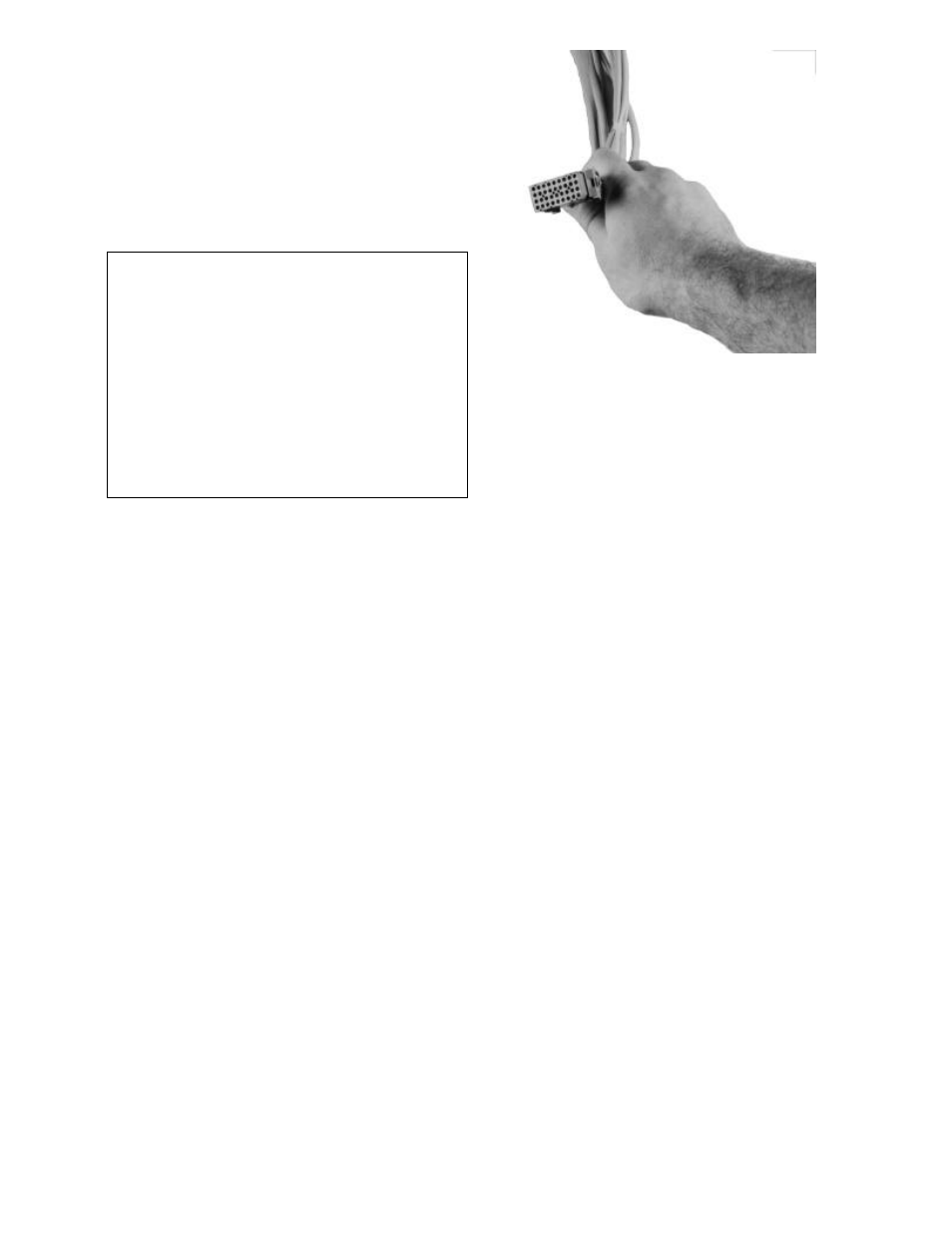
Step 1.
Slide the adapter bracket onto the 36-pin
programmer connector (Figs. 1a & 1b). Be sure
that the beveled corners of the programmer
connector are facing toward the right side, the
adapter bracket slides in place behind the notches
on either side of the connector body, and that the
connector’s tabs align with the notches provided
on the bottom of the adapter bracket.
Step 2.
Hold the adapter bracket tight to the programmer
connector and bend the two (2) locking tabs
provided on the adapter bracket over the
connector body (Fig. 1c).
Fig. 1a. 36-Pin Programmer Connector
Fig. 1b. Adapter Bracket
Fig. 1c. Adapter Bracket Locking Tabs