10 error detection, Astat-sd – GE Industrial Solutions ASTAT-SD Solid-State Reduced Voltage Starter User Manual
Page 17
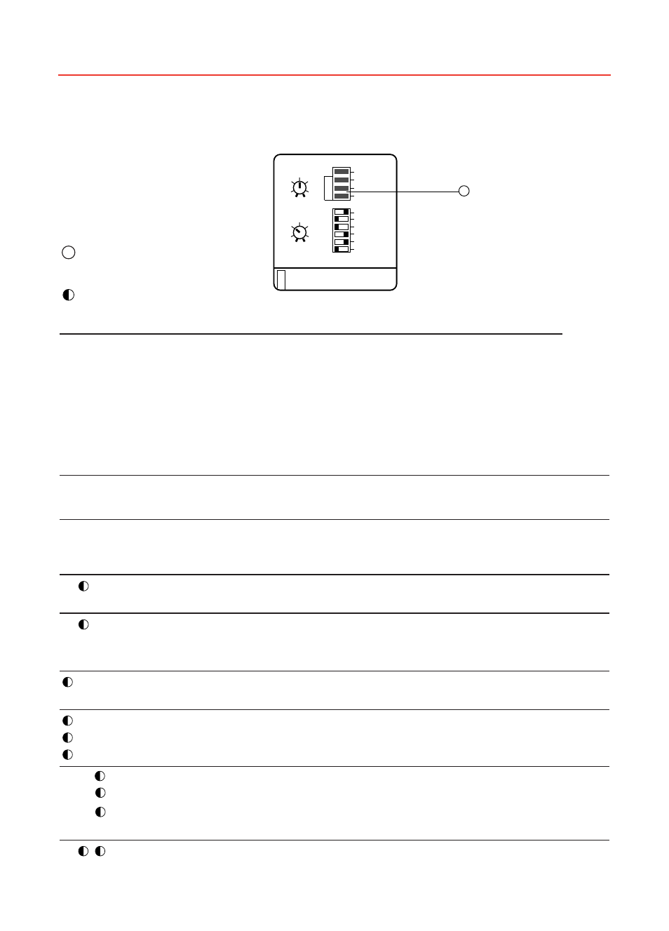
2-10 Error detection
LEDs
●
●
OFF
●
ON
BLINKING
O
A
B
C
OPERATION CODE
●
●
●
●
●
●
●
Equipment is connected to main supply
●
●
●
●
●
●
Run
●
●
●
●
●
End of ramp
●
●
●
●
Effective energy saving
●
●
●
●
●
●
Stop order
ASTAT-SD
™
Solid-State Reduced Voltage Starters
Chapter 2. Installation & Start-up
13
30
40
20
50
10
0.5 60
50
4/60
3/40
70
30
2/15 5/80
RAMP(s)
WHEN BLINKING SEE ERROR CODE
ILT/TORQUE
A
B
C
A
0
B
C
RUN
ON
FULL
SAVE
ILT/TORQUE
HD/SD
1 0
KICK START
SOFT STOP
EOR/RUN
OVERRIDE
1
1
LEDs
A B C
Symptom or Error
Possible Cause
Measures to be Taken
LED “O” off
No control voltage
Check wire harness and control voltage
Defective control PCB,s
Change control PCB,s
Equipment does not
Defective control PCB,s
Change control PCB,s
respond to STOP/
START controls
●
●
●
Frequency error
No 1L1 phase of frequency
Check 1L1 phase and/or main
48Hz
frequency
●
●
Phase sequence loss Disturbance in supply voltage Check notches or dropouts in power line
Defective thyristor
Check thyristors
No input phases
Check 1L1, 3L2 and 5L3 phases
●
● ●
●
Synchronism loss
Phase 1L1 lost
Check 1L1 phase, ground connection
and/or output voltage to ground
●
●
●
A Phase A, B, C
Short-circuited thyristor
Check thyristor module
●
●
● B thyristor
No output phases
Check 2T1, 4T2 and 6T3 phases
● ● C
●
●
●
A Phase A, B, C lost
No input/output phases
Check power wire harness for
●
●
●
B
1L1, 3L2, 5L3, 2T1, 4T2 and 6T3
● ●
C
Defective thyristor or bad
Verify gate and cathode wire
wire harness
harness and verify thyristors
●
Internal failure
Microcontroller malfunction
Check that IC2 is correctly inserted
in socket