Locating failed fans – GE Industrial Solutions CPS3200U User Manual
Page 11
11
TECHNICAL SUPPORT GUIDE CC84885345
CPS3200U, QS982A, QS941A, Upstream Systems
3.
QS941
4.
Alarm Card
5.
Converter Card
6.
Human Response
1.
Alarm
Display
2.
What it
means
LED
State
Relay
State
Alarm
LED
State
Relay
State
OK
LED
State
Alarm
LED
State
Corrective Action
Input Power
B9-16
Power Fail
Yellow
Min B
Red Min Green Off
Reconnect DC input power
flowing to the B9-16 input
terminal.
Input Power
Mul Circuit
Fail
A1-8 & B1-
8 Power
Fail
Red Maj A
Red
B Red
Maj
Green
Off
Reconnect DC input power
flowing to the A1-8 input
terminal and Reconnect DC
input power flowing to the B1-
8 input terminal
Input Power
Mul Circuit
Fail
A9-16 &
B9-16
Power Fail
Red Maj A
Red
B Red
Maj
Green
Off
Reconnect DC input power
flowing to the A9-16 input
terminal. Reconnect DC input
power flowing to the B9-16
input terminal.
Load Drop
Load Drop
Yellow
Min
A, B & OK
Green
Green
Off
Check the integrity of the
circuits going to the load. Or
Adjust load drop threshold to
0 to disable this feature.
Load Share
As set of
circuits
assigned to
one remote
destination
are not
sharing
current as
would be
expected .
Yellow
Min
A, B & OK
Green
Green
Off
Check the integrity of the
circuits going to the load. Or
Adjust load share threshold to
disable this feature.
Line Test
OK, Fail or
Aborted
A, B & OK
Green
Green
Off
Estimated line resistance has
increased since last
measurement.
Loss Of
Redundancy
Yellow
Min
A, B & OK
Green
Green
Off
The loss of n additional
circuits will cause customers
to lose service. Check
redundancy threshold in the
configuration.
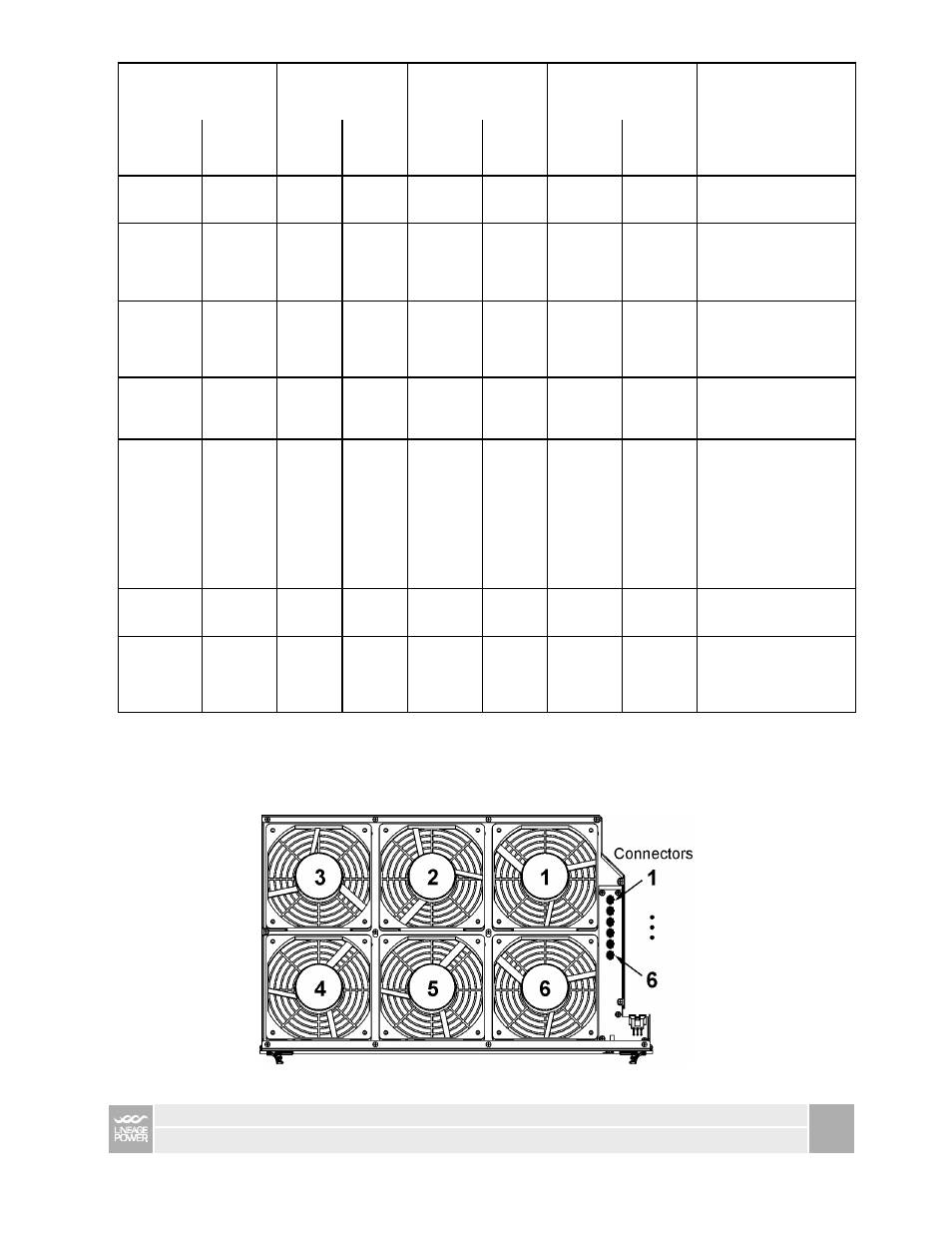
Locating Failed Fans
Fan failures within a tray can be found by correlating the number of LED flashes to this map: