Alarm reference table – GE Industrial Solutions CPS3200U User Manual
Page 10
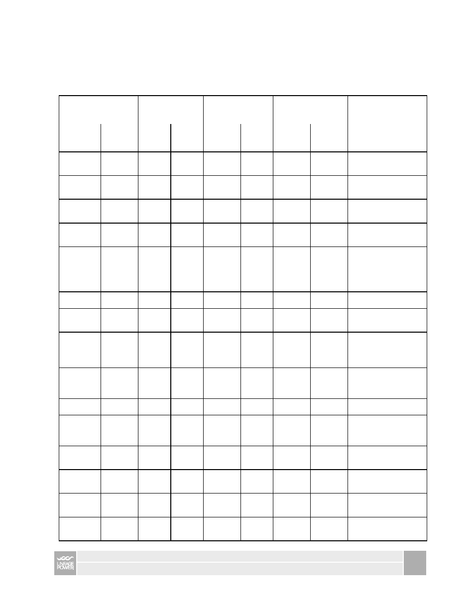
Alarm Reference Table
This Alarm Table shows how FTTN Alarms are categorized by the QS941 Controller. Many alarms are
best processed at the converter shelf alarm card and converter card level. In other words columns 4, and
5, can be used to select the appropriate action from column 6.
[QS941 Controller Page 27]
3.
QS941
4.
Alarm Card
5.
Converter Card
6.
Human Response
1.
Alarm
Display
2.
What it
means
LED
State
Relay
State
Alarm
LED
State
Relay
State
OK
LED
State
Alarm
LED
State
Corrective Action
Circuit Fail
Short + to -
Yellow
Min Yellow Min Green Flashing
Yellow
Make sure each converter
has an independent isolated
send and return path.
Circuit Fail
Short to
Ground
Yellow
Min Yellow Min Flashing
Red
Flashing
Red
Make sure each converter
has an independent isolated
send and return path.
Comm. Fail
1 Card
Removed
Yellow
Min
Yellow
Min
Green
Off
Check to see that all cards
are seated. Replace non-
functioning cards.
Comm. Fail
2 Cards
Removed
Red
Maj
Check to see that all cards
are seated. Replace non-
functioning cards.
Comm. Fail
Comm.
Cable
Removed
Red Maj Flashing
Red
Green
Off
Check communication path
from alarm cards to QS941
controller. If no controller is
present, set alarm card rotary
switch to position 0 for contact
closures only communication.
Comm. Fail
Alarm Card
Removed
Red
Maj
Green
Flashing
Red
Replace Alarm card.
None
Standby
Green
Green
Yellow
Remove unit from standby if
desired using QS941 or
Ethernet interface
Circuit Fail
Open Fuse
Yellow
Min Yellow Min Green Flashing
Yellow
Replace unit. Note: Restoring
service to one line will
interrupt service to the other
line served by that card.
Circuit Fail
Under
Voltage
Yellow
Min Yellow Min
Flashing
Yellow
Replace unit. Note: Restoring
service to one line will
interrupt service to the other
line served by that card.
Fan Fail
1 Fan Tray
Failed
Yellow
Min Yellow Min Green Off Replace
fan
tray.
Fan Fail
1 of 6 fans
Failed on
one Fan
Tray
Yellow
Min Yellow Min Green Off Replace
fan
tray.
Fan Fail
2 Fan
Trays
Failed
Red Maj Red Maj Green Off Replace
fan
trays.
Input Power
A1-8
Power Fail
Yellow
Min A
Red Min Green Off
Reconnect DC input power
flowing to the A1-8 input
terminal.
Input Power
B1-8
Power Fail
Yellow
Min B
Red Min Green Off
Reconnect DC input power
flowing to the B1-8 input
terminal
Input Power
A9-16
Power Fail
Yellow
Min A
Red Min Green Off
Reconnect DC input power
flowing to the A9-16 input
terminal
TECHNICAL SUPPORT GUIDE CC84885345
CPS3200U, QS982A, QS941A, Upstream Systems
10