GE Industrial Solutions Power Break II Motor Operator User Manual
Page 6
Power Break® II Motor Operator Mechanism
Installation in 800–2000 A Draw-Out Breaker
6
1
1
1
1 1
1
1
1 .... Loosen the four screws at the corners of the breaker
cover. Crank the operating handle one time and
hold it extended to remove the cover from the
breaker face, as illustrated in Figure 3. The Motor
Operator can be safely installed with such a
partially charged mechanism.
1
1
1
1 2
2
2
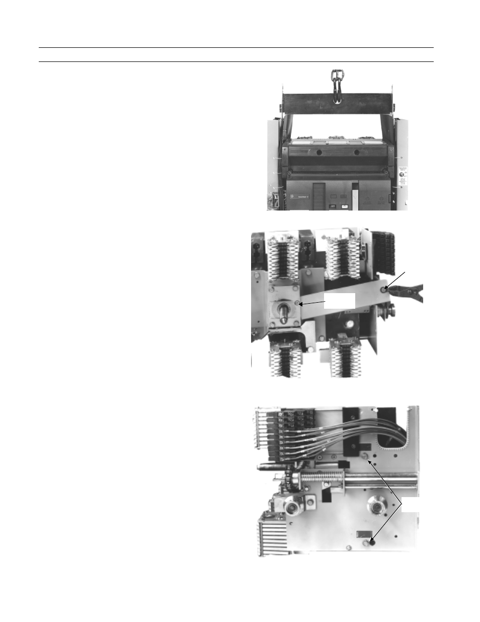
2 .... Remove the retaining screw and snap ring (using
an appropriate snap ring pliers) that hold the
chain guard in place on the rear of the breaker, as
shown in Figure 12, then remove the guard.
1
1
1
1 3
3
3
3 .... Remove the two screws holding the breaker side
plate in place, as shown in Figure 13.
1
1
1
1 4
4
4
4 .... Tilt the side plate away from the breaker, then
remove the racking chain from the gear, as shown
in Figure 14.
1
1
1
1 5
5
5
5 .... Remove the screw holding the secondary terminal
block to the midcover, as illustrated in Figure 15,
and lift the terminal block up and away from its
mounting ridge.
1
1
1
1 6
6
6
6 .... Turn the breaker so that it is resting on the
primary disconnects, as illustrated in Figure 16. Be
careful not to lose the white nylon plunger that will
fall out from the back of the breaker, as it must be
reinstalled when the breaker is reassembled.
1
1
1
1 7
7
7
7 .... Follow steps 8 to 17 in the installation procedure
for the stationary breaker.
1
1
1
1 8
8
8
8 .... Turn the breaker to its original position, carefully
reinserting the nylon plunger in the rear of the
breaker.
1
1
1
1 9
9
9
9 .... Replace the chain on the gear, then tilt the side
plate back into place. Replace the two mounting
screws, tightening them to 70 in-lb.
2
2
2
2 0
0
0
0 .... Replace the chain guard and fasten it in place with
the retaining screw and snap ring removed earlier.
2
2
2
2 1
1
1
1 .... Crank the operating handle once and hold the
handle extended to reinstall the breaker top cover.
Tighten the four #10-32 mounting screws to 15 in-
lb.
2
2
2
2 2
2
2
2 .... Replace the trim plate and tighten the four #8-32
screws to 20 in-lb.
2
2
2
2 3
3
3
3 .... Affix the accessory rating label to the breaker cover
above the right-side secondary terminal block.
2
2
2
2 4
4
4
4 .... Affix the “Electrically Operated” label to the top
cover over the knock-out space above the ON-OFF
indicator flag.
2
2
2
2 5
5
5
5 .... Crank the operating handle until the closing
springs are completely charged.
2
2
2
2 6
6
6
6 .... Close and trip the breaker.
2
2
2
2 7
7
7
7 .... Test the Motor Operator Mechanism electrically
according to Table 1.
Figure 11. Lifting Bar attached to the breaker for lifting with a hoist.
Figure 12. Locations of the retaining screw and snap ring on the chain
guard.
Figure 13. Two screws to be removed from the breaker side plate.
Snap
Ring
Retaining
Screw
Side Plate
Screws