GE Industrial Solutions Power Break II Motor Operator User Manual
Page 10
Power Break® II Motor Operator Mechanism
Installation in 2500–4000 A Draw-Out Breaker
10
2
2
2
2 6
6
6
6 .... Line up the bottom mounting tab on the breaker
side plate with the raised retainer on the side of
the breaker, then hit the bottom of the lip at the
front of the side plate with a rubber mallet to seat
the tab. Line up the upper tab with its retainer and
hit the top of the side plate lip with the mallet to
seat the tab.
2
2
2
2 7
7
7
7 .... Attach the two bolts, nuts, and lock washers
holding the side frame to the breaker and tighten
to 300 in-lb.
2
2
2
2 8
8
8
8 .... Attach the clip to the upper mounting tab retainer
with the screw removed earlier.
2
2
2
2 9
9
9
9 .... Put the chain back on its drive gear and hold it in
place with the two parts of the removable link. With
a screwdriver blade, pry the retaining clip apart
and slide it over the two exposed pins, as shown in
Figure 18 (the reverse of removal).
3
3
3
3 0
0
0
0 .... Ensure that the white nylon interlock plunger is
properly installed in the rear of the breaker.
Replace the chain guard and fasten it in place
with the retaining screw and snap ring removed
earlier.
3
3
3
3 1
1
1
1 .... Slide the two steel rods through the holes in the
secondary disconnect and into the mounting holes
in the side frame. Insert the other ends of the rods
into the mounting bar and attach the bar to the
side plate with the two screws removed earlier.
3
3
3
3 2
2
2
2 .... Crank the operating handle once and hold the
handle extended to reinstall the breaker top cover.
Tighten the four #10-32 mounting screws to 15 in-
lb.
3
3
3
3 3
3
3
3 .... Replace the trim plate and tighten the four #8-32
screws to 20 in-lb.
3
3
3
3 4
4
4
4 .... Affix the accessory rating label to the breaker cover
above the right-side secondary terminal block.
3
3
3
3 5
5
5
5 .... Affix the “Electrically Operated” label to the top
cover over the knock-out space above the ON-OFF
indicator flag.
3
3
3
3 6
6
6
6 .... Crank the operating handle until the closing
springs are completely charged.
3
3
3
3 7
7
7
7 .... Close and trip the breaker.
3
3
3
3 8
8
8
8 .... Test the Motor Operator Mechanism electrically
according to Table 1.
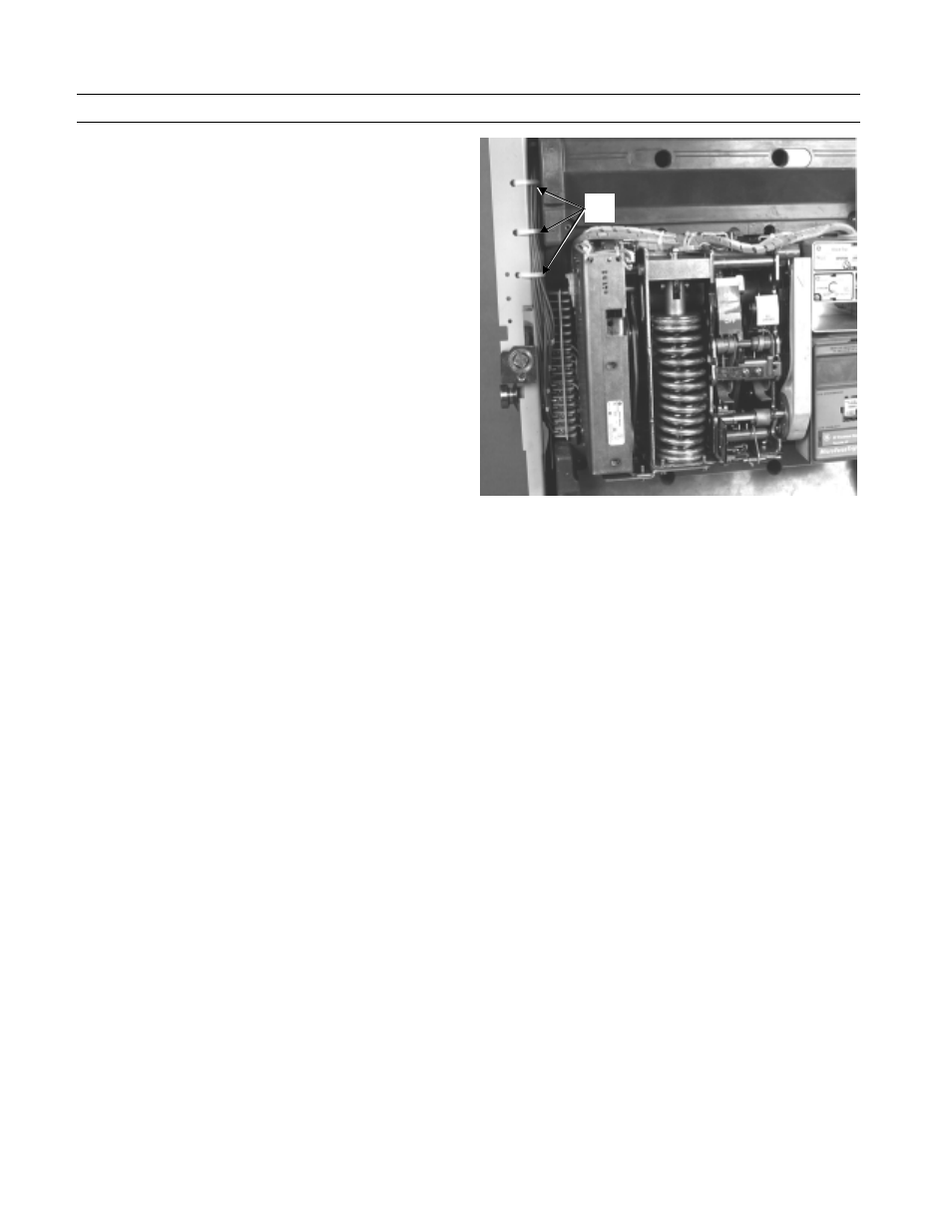
Figure 21. Motor Operator Mechanism installed in the breaker, showing
the side panel reattached and the cable ties replaced on the wires
connecting the terminal block to the secondary disconnect.
Wir
e