GE Industrial Solutions Power Break II Motor Operator User Manual
Page 3
Power Break® II Motor Operator Mechanism
Installation in 800–4000 A Stationary Breaker
3
onto the breaker until the spacers engage the
spring frame and the stop block.
1
1
1
1 2
2
2
2 .... Attach the Mounting Bracket to the four holes
opposite the stop block on the spring frame with
#10-32 screws tightened to 32 in-lb torque. The
bend of the bracket must be outward from the
spring frame.
1
1
1
1 3
3
3
3 .... Align the two holes in the Mounting Bracket with
the two holes in the Motor Operator Mechanism
and attach with two #10-32 screws tightened to 32
in-lb torque.
1
1
1
1 4
4
4
4 .... Thread a
1
⁄
4
–20 flat-head screw and conical lock
washer through the spacer and into the stop block,
as illustrated in Figure 4. Thread the other
1
⁄
4
–20
flat-head screw and conical lock washer through
the spacer into the captive nut in the spring frame.
Tighten both screws to 70 in-lb.
1
1
1
1 5
5
5
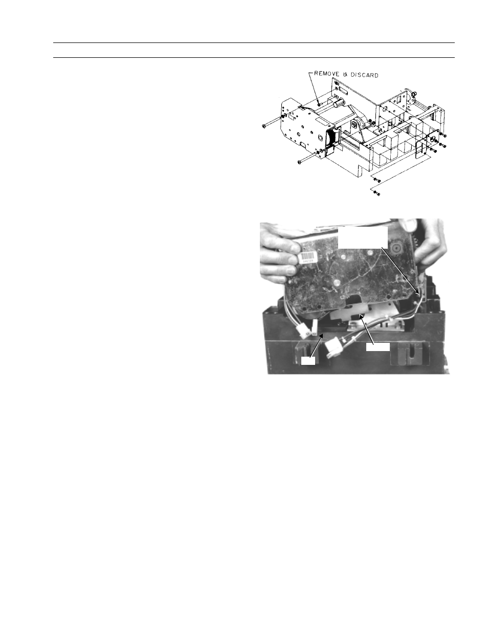
5 .... Plug the color-coded, numbered Motor Operator
Mechanism wires into the corresponding num-
bered sockets, as illustrated in Figure 6. Mating
connector wires are installed at the factory and are
located in the gray-painted channel, shown in
Figure 5
1
1
1
1 6
6
6
6 .... Dress the wires and install cable ties as shown in
the illustration in Figure 7. Ensure that wires are
clear of all moving parts.
1
1
1
1 7
7
7
7 .... Reinstall the secondary terminal block onto the
breaker midcover terminal block mounting ridge
and fasten with the screw previously removed.
1
1
1
1 8
8
8
8 .... Crank the operating handle once and hold the
handle extended to reinstall the breaker top cover.
Tighten the four #10-32 mounting screws to 15 in-
lb.
1
1
1
1 9
9
9
9 .... Replace the trim plate and tighten the four #8-32
screws to 20 in-lb.
2
2
2
2 0
0
0
0 .... Affix the accessory rating label to the breaker cover
above the right-side secondary terminal block.
2
2
2
2 1
1
1
1 .... Affix the “Electrically Operated” label to the top
cover over the knock-out space above the ON-OFF
indicator flag.
2
2
2
2 2
2
2
2 .... Crank the operating handle until the closing
springs are completely charged.
2
2
2
2 3
3
3
3 .... Close and trip the breaker.
2
2
2
2 4
4
4
4 .... Test the Motor Operator Mechanism electrically
according to Table 1.
Figure 4. Installing the Motor Operator Mechanism onto the breaker.
Figure 5. Rotating the Motor Operator Mechanism so that the guard
clears the lip on the side of the circuit breaker.
Motor Operator
Wires in Gray
Channel
Guard
Lip