GE Industrial Solutions Power Break II Motor Operator User Manual
Page 2
Power Break® II Motor Operator Mechanism
Installation in 800–4000 A Stationary Breaker
2
Installation in 800–4000 A Stationary
Breaker
W
W
W
W A
A
A
A R
R
R
R N
N
N
N IIIIN
N
N
N G
G
G
G ::::
Before installing any accessories, turn the
breaker off, disconnect it from all voltage sources, and
discharge the closing springs.
A
A
A
AV
V
V
VE
E
E
ER
R
R
RT
T
T
TIIIISSS
SSSS
SE
E
E
EM
M
M
ME
E
E
EN
N
N
NT
T
T
T::::
Avant d’installer tout accessoire,
mettre le disjoncteur en position OFF, le déconnecter de
toute tension d’alimentation, et décharger les ressorts
d’armement.
Use the following procedure to install the Motor Operator
Mechanism onto a stationary circuit breaker.
1
1
1
1 .... Verify that the rating on the Motor Operator
Mechanism identification plate matches the
voltage rating required for the application, as
listed in Table 1.
2
2
2
2 .... Check that the package contains all the parts listed
in Table 2. If any components are missing, contact
the ED&C Customer Support Center at 800-843-
3742. Note that the Remote Close and Shunt Trip
accessories are not included with the Motor
Operator Mechanism; they must be ordered
separately.
D
D
D
De
e
e
esss
sccc
crrrriiiip
p
p
pttttiiiio
o
o
on
n
n
n
Q
Q
Q
Qu
u
u
uaa
a
an
n
n
nttttiiiittttyyy
y
Motor Operator Assembly
1
1
⁄
4
-20 x 3-inch Flat-Head Screw
2
1
⁄
4
-inch Conical Lock Washer
2
Mounting Bracket
1
#10-32 x
1
⁄
4
inch Screw
6
#10 Lock Washer
6
Labels
2
Table 2. Parts list for the Motor Operator Mechanism.
3
3
3
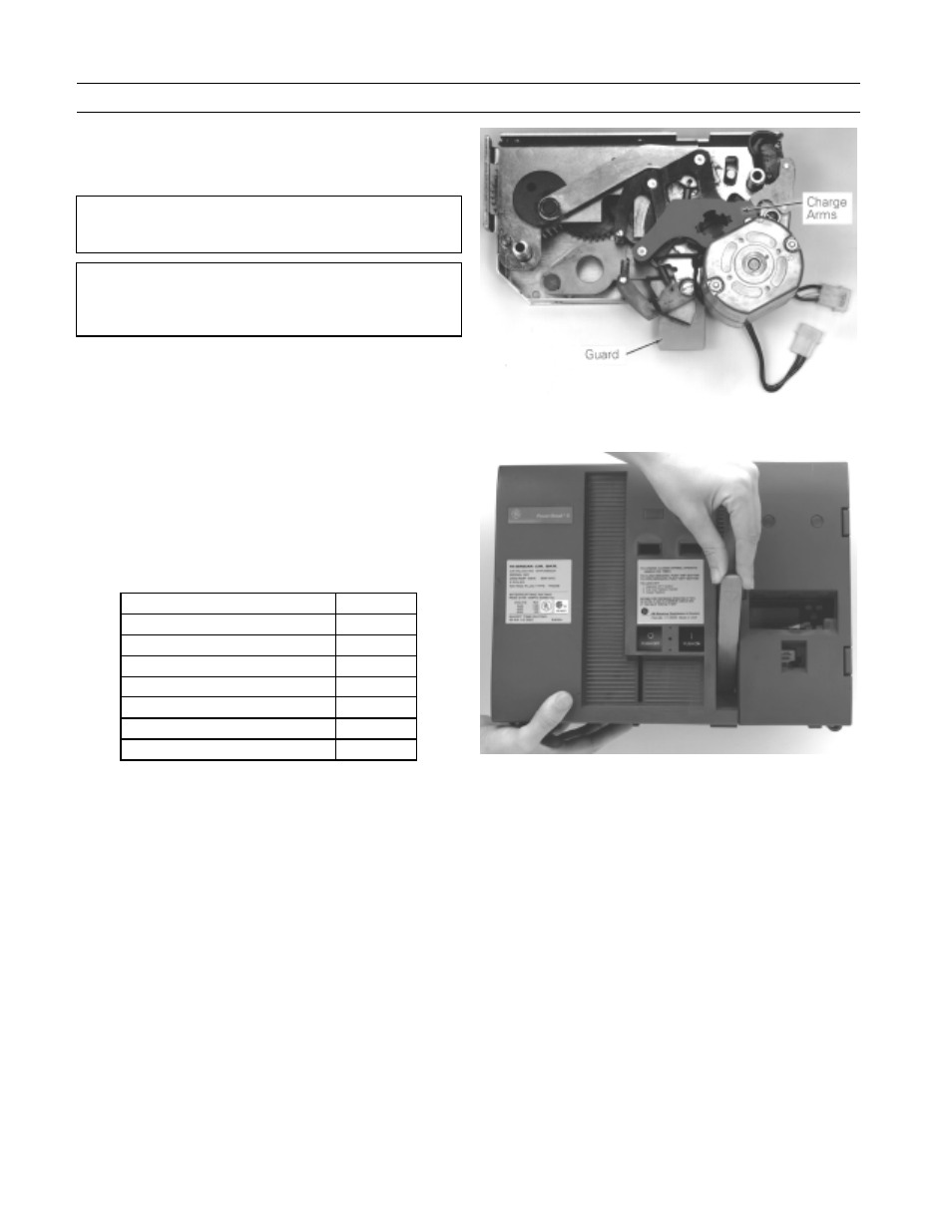
3 .... Verify that the charge arms of the Motor Operator
Mechanism are in the discharged position, as
illustrated in Figure 2.
4
4
4
4 .... Turn the breaker off and discharge the closing
spring by depressing the OFF and ON buttons in
the sequence OFF-ON-OFF. Verify that the breaker
OFF-ON indicator shows OFF on a green
background and that the charge indicator shows
DISCHARGED on a white background.
5
5
5
5 .... Loosen the four #8-32 screws on the trim-plate
assembly and remove the trim plate.
6
6
6
6 .... Loosen the four screws at the corners of the breaker
cover. Crank the operating handle one time and
hold it extended to remove the cover from the
breaker face, as illustrated in Figure 3. The Motor
Operator can be safely installed with such a
partially charged mechanism.
Figure 2. Motor Operator Mechanism charge arms in the discharged
position.
Figure 3. Removal of the breaker top cover.
7
7
7
7 .... Remove the screw holding the left secondary
terminal block to the midcover and lift the ter-
minal block up and away from its mounting ridge
on the midcover.
8
8
8
8 .... Install the Remote Close accessory at this time if
the breaker is to be equipped with this option.
9
9
9
9 .... R
R
R
Reee
em
m
m
mo
o
o
ovvvveee
e aa
a
an
n
n
nd
d
d
d d
d
d
diiiissssccc
caa
a
arrrrd
d
d
d tttth
h
h
heee
e b
b
b
bo
o
o
otttttttto
o
o
om
m
m
m ssss ccc
c rrrr eee
e w
w
w
w ,,,,
ssssh
h
h
ho
o
o
ow
w
w
wn
n
n
n iiiin
n
n
n F
F
F
Fiiiig
g
g
gu
u
u
urrrreee
e 4
4
4
4,,,, tttth
h
h
haa
a
atttt aa
a
attttttttaa
a
accc
ch
h
h
heee
essss tttth
h
h
heee
e sssstttto
o
o
o p
p
p
p
b
b
b
bllllo
o
o
occc
ckk
k
k tttto
o
o
o tttth
h
h
heee
e ssssp
p
p
prrrriiiin
n
n
ng
g
g
g ffffrrrraa
a
am
m
m
meee
e....
1
1
1
1 0
0
0
0 .... Position the charge interlock rod of the breaker
down against the midcover.
1
1
1
1 1
1
1
1 .... While holding the charge arm of the Motor
Operator Mechanism in the discharged position,
align the splined closing shaft of the breaker with
the splined cutout in the hub of the charge arm, as
shown in Figure 4. Tilt the right end of the
mechanism up so that the guard (see Figure 2)
clears the lip on the side of the breaker, as shown
in Figure 5. Push the Motor Operator Mechanism
in past the lip, rotate it back down, then push it