Application, Introduction, Three-wire connection – GE Industrial Solutions A Series Lighting Control Panelboards Remote Switch Expansion Module ASRGLCDSK User Manual
Page 3
3
Application
This installation guide applies to the Lighting Controller
expansion module (cat. no. ASRGLCDSK), as illustrated
on the cover.
Introduction
The A Series
®
Lighting Controller accepts 16 switch
inputs from the standard module, shown in Figure 1.
Figure 1. A Series lighting controller with standard input module.
The standard module is mounted on the controller and
draws power from it. Additionally, the lighting controller
can also accept remote switch inputs from the remote
input expansion module, which has 16 switch inputs.
These modules are referred to as standard and remote in
this guide.
The remote module needs a separate 24 Vac/dc supply to
power it. NET2 on the controller board is connected to
the communication port of the remote module.
These modules use the LINKnet communications
protocol. Up to 12 LINKnet devices can be connected to
one controller. These modules handle inputs exclusively.
There are three pins per input labeled
ON
,
COM
, and
OFF
.
These modules are designed to convert three analog input
values to the digital values 0, 2048, and 4096.
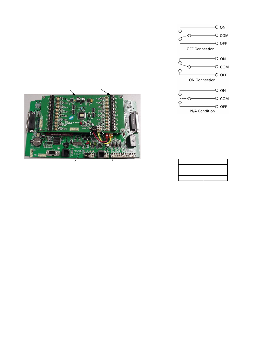
Three-Wire Connection
The three-wire connection states are shown in Figure 3.
Figure 2. Three-wire input connections.
Operation
The input voltage is converted to the corresponding
digital value listed in Table 1. If a connection is
made between all three of the input pins (shorting
ON
,
COM
, and OFF) the controller goes to OFF state.
Input, V
Output
0
0
2.5
2048
5.0
4096
Table 1. Analog-to-digital conversion of voltages.
Momentary Inputs
The following rules apply to momentary inputs:
• All-state changing pulses must be sustained for 100
milliseconds or more.
• A multistate (MI) object must be used to determine
the input states.
• When the MI object transitions to
ON
from
OFF
or
N/A
condition, the corresponding BV object toggles.
MI 101 corresponding to BV 101, MI102
corresponding to BV102, and so on.
Maintained Inputs
A multistate (MI) object can capture maintained input
states. The multistate input (MI) object requires a
multistate input configuration (MIC) object to define
which input values determine a state change.
Standard Module
Inputs
Power
S
l
Communication