Figure 12 – GE Industrial Solutions Power Break II Replacment Stop Block Kit User Manual
Page 4
handle side of the assembly wall (Figure 10). If Electric
Operator is installed, then only the front and handle side
bolts will need to be removed because the rear bolt will
not be installed.
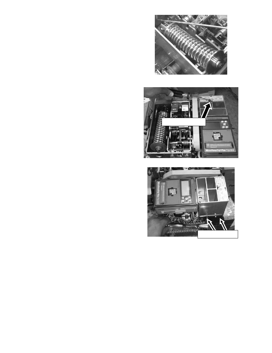
12. Loosen any screws on the front face of the accessories
(Figure 13) until the screws are fully loosened from the
housing, and then loosen the ¼-in setscrews located on
the side of the shunt trip guide housing (Figure 14). This
will allow the guide housing and accessories to be
removed.
13. Using the supplied
5
/
32
Allen Wrench [6], unscrew the
long bolt (BH HEX SKT
1
/
4
-20 X 3.56 SCREW) located on
the structure as seen in Figure 15 from the stop block
but it is not necessary to fully remove from the Spacer
Side Frame Pin tubing with collar that it passes through.
14. Wedge a flat head screwdriver between the spring
frame bearing and shaft and then rotate 90 degrees in
order to deflect the left side of the spring assembly wall
outward (Figure 16) to allow for the removal of the stop
block (Figure 17).
15. Discard the currently installed stop block, replace with
the new stop block assembly [3], and secure with the
three new Bolts with nylon patch [4] with Steel Spring
Lock Washers [5] on each to 65 inch-pounds min. For
models with the Electric Operator only replace the front
and handle side bolts. Ensure that the holes in the new
stop block align with the screw holes in the assembly to
avoid installing the new stop block incorrectly. Looking
at the block with the stop block gasket facing down,
there should be three holes on the left side of the stop
block and two holes on the right side.
16. Screw in the long bolt as seen in Figure 15 with a
5
/
32
Allen Wrench [6] to 90 inch-pounds min., and secure the
Shunt Trip guide casing and unit back into place.
17. Align the charging spring back in position, as shown in
18. Operate the breaker-charging handle five times.
Remove the spring assembly screw [1] and spacer [2]
from the end of the spring.
19. Press on the close de-latch lever with a screwdriver,
rotating it clockwise as seen from the handle side of the
breaker, as shown in Figure 19. Then, with another
screwdriver, rotate the close de-latch mechanism to
release the charging pawl.
20. Rotate the trip de-latch lever fully back against the
frame, as shown in Figure 20, while pressing down on
the cradle to release the closing mechanism. While
holding the cradle down, rotate the spring forward
against the stop block.
Figure 12: Spring Removed Up and Out of Assembly.
Shunt Trip Screw
Figure 13:Shunt Trip Screw to be Unscrewed
Figure 14: 2 Setscrews
¼-in Setscrews