In figure 8, Figure 10). while hol, N in figure 11 – GE Industrial Solutions Power Break II Replacment Stop Block Kit User Manual
Page 3
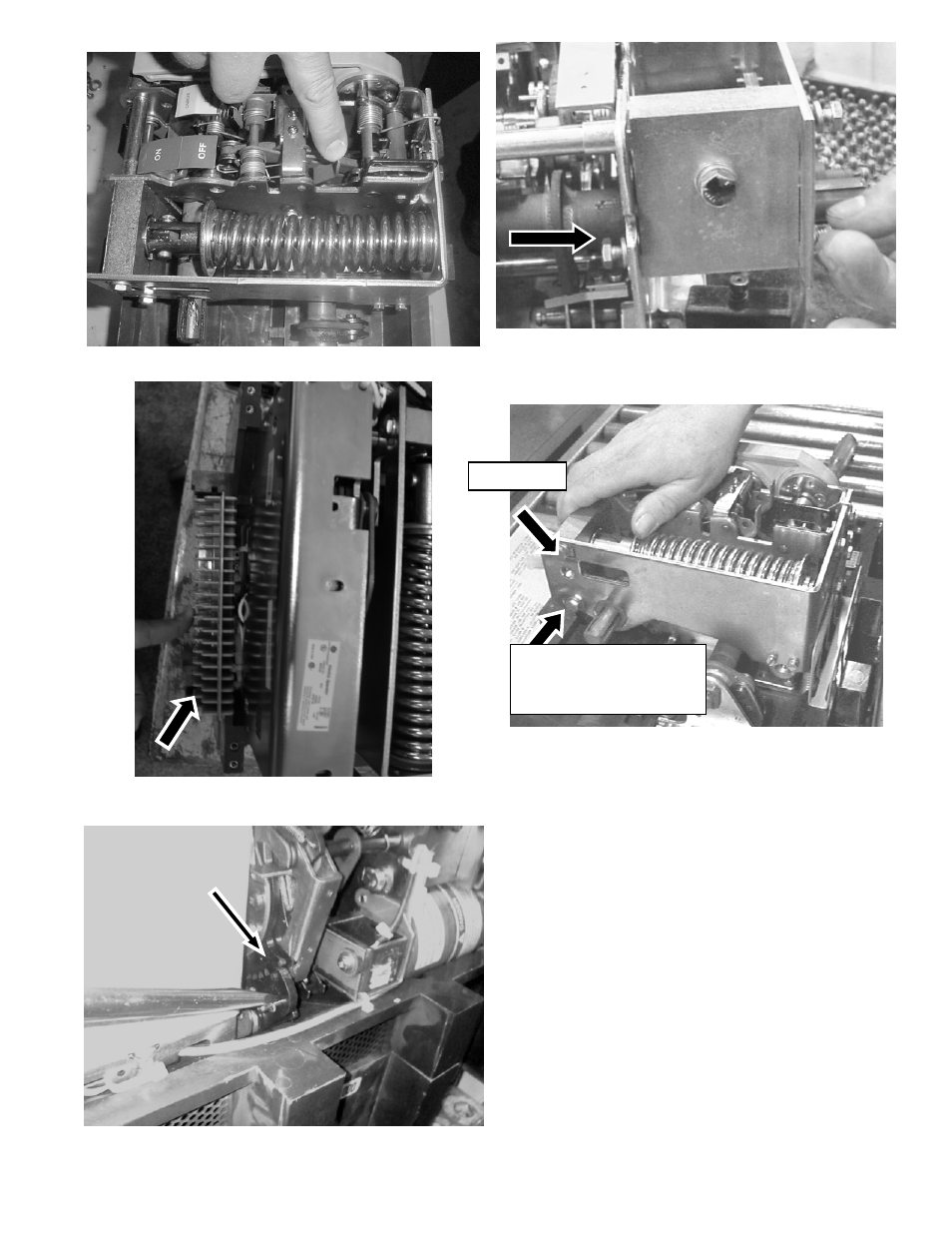
Figure 7: Illustration of Bolt on Handle Side of Assembly
Wall
Figure 8: Releasing the breaker mechanism.
Figure 9: Secondary Connections Piece to be Removed Before
Electric Operator
Figure 10: Illustration of ratchet arm being pulled away from
sprocket
Front Bolt
Figure 11: Pressing the spring assembly to allow removal.
Rear Bolt
(Not Present with
Electric Operator
9. If the Electric Operator is installed on a stationary
breaker it must be detached before the Stop Block is
replaced. First remove the gray plastic secondary
connection piece from the left side of the breaker (Figure
9). Remove the two long Phillips screws and external
tooth lock washers from the left side of the Electric
Operator (Figure 22 & Figure 23) with a #3 Phillips
screwdriver.
10. If working on the stationary model, support the Electric
Operator with your hand so it does not fall following the
next step. Remove the two smaller hex screws and split
lock washers from the silver bottom plate that secures
the Electric Operator to the assembly walls (Figure 23).
The Electric Operator may now be set-aside without
disconnecting the electric snap connections. The Draw-
out model only requires that the electric operator be slid
to the left slightly allowing for a
7
/
16
wrench to access
the bolt on the side of the assembly wall (Figure 21 &
11. Remove the front and rear bolts that secure the stop
block to the left side of the spring assembly wall (Figure
11), and the bolt securing the stop block assembly to the