GE Industrial Solutions Power Break II Replacment Stop Block Kit User Manual
Power break, Installation
DEH40466 Installation Instructions
R04
g
Power
Break
®
II Circuit Breakers
Replacement Stop Block Kit
Application
This kit is provided to replace the stop block assembly in the
Power Break II insulated-case circuit breakers. The parts
included in this kit are illustrated in Figure 1 and listed in Table
1. In the following instructions and figures, numbers in
brackets refer to the items in Table 1.
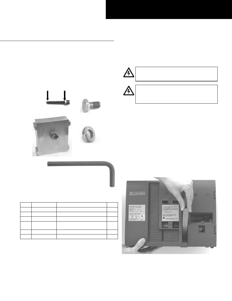
Figure 1:Parts included in the stop block gasket kit
Item Part
# Description
Qty.
1
N170P19024 SPRING ASSEMBLY SCREW
1
2 192A6368P1
SPACER
1
3
10054595G1 ASSEMBLY, STOP BLOCK
1
4
192A6976P233 BOLT, N22P21008B6 W/NYLON
PATCH
4
5
N405P41B6
LOCKWASHER, STL SPRING 1/4
4
6
10103378P1 5/32 ALLEN WRENCH TOOL
1
Table 1. Parts list for the stop block gasket kit.
Installation
WARNING: Before beginning this procedure, turn
the breaker
OFF
, disconnect it from all voltage
sources, and discharge the closing springs.
AVERTISSEMENT: Mettre le disjoncteur à
OFF
, le
débrancher de toutes les sources de tension et
déclencher les ressorts de fermeture avant
d'entamer cette procédure.
[1]
[2]
1. Turn the breaker off and discharge the closing spring by
depressing the
OFF
and
ON
buttons in the sequence
OFF-
ON-OFF
. Verify that the breaker
OFF-ON
indicator shows
OFF
on a green background and that the charge
indicator shows
DISCHARGED
on a white background.
[4]
[5]
2. A draw-out and stationary-mounted breaker need not
be removed from their enclosures, but be careful that all
primary and control power to the breakers are
disconnected.
[3]
3. Loosen the four #8-32 screws that attach the trim plate
to the breaker, if present, and remove the trim plate.
4. Loosen the four screws at the corners of the breaker
cover. Operate the charging handle one time and hold it
extended to remove the cover from the breaker face, as
illustrated in Figure 2.
[6]
Figure 2: Removing or installing the breaker top cover.