GE Industrial Solutions Power Break II Replacment Stop Block Kit User Manual
Page 2
5. Operate the charging handle four more times (for a total
of five, one less than the six needed to fully charge the
closing spring). If the closing spring does not charge, use
the following steps:
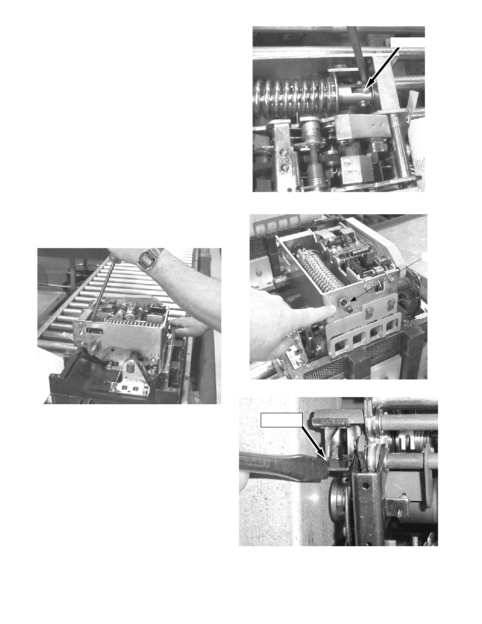
a. With a large screwdriver, put pressure on the end of
the closing spring, as shown in Figure 3 and Figure 4.
b. Maintain pressure with the screwdriver while
operating the charging handle one time.
c. Remove the screwdriver and operate the handle four
more times.
6. Install the spring assembly screw [1] with spacer [2] at
the end of the spring assembly, as shown in Figure 5
with the supplied
5
/
32
Allen Wrench tool [6].
7. Release the closing spring by pressing the close de-latch
lever with a screwdriver, as shown in Figure 6. Then
press the lever nearest the spring to release the breaker
mechanism, as shown in Figure 8.
8. Using a screwdriver pull the ratchet arm away from the
sprocket to allow for the shaft mechanism to rotate
freely (Figure 10). While holding the ratchet arm away
from the sprocket, press the spring against the stop
block as shown in Figure 11, then lift the front end of the
spring assembly up and out, as shown in Figure 12.
Figure 3: Applying pressure to the end of the closing spring.
Figure 4: Application point of screwdriver.
Screwdriver
[1, 2]
Figure 5: Installing the spring assembly screw.
Close De-latch
Lever
Figure 6: Pressing the close de-latch lever to release the
closing spring.