Data sheet, Feature descriptions (continued) – GE Industrial Solutions EBVW020A0B Barracuda Series User Manual
Page 9
GE
Data Sheet
EBVW020A0B Barracuda Series; DC-DC Converter Power Modules
36-75Vdc Input; 12.0Vdc, 20.0A, 240W Output
July 22, 2013
©2012 General Electric Company. All rights reserved.
Page 9
Feature Descriptions (continued)
Remote Sense (“9” Option Code)
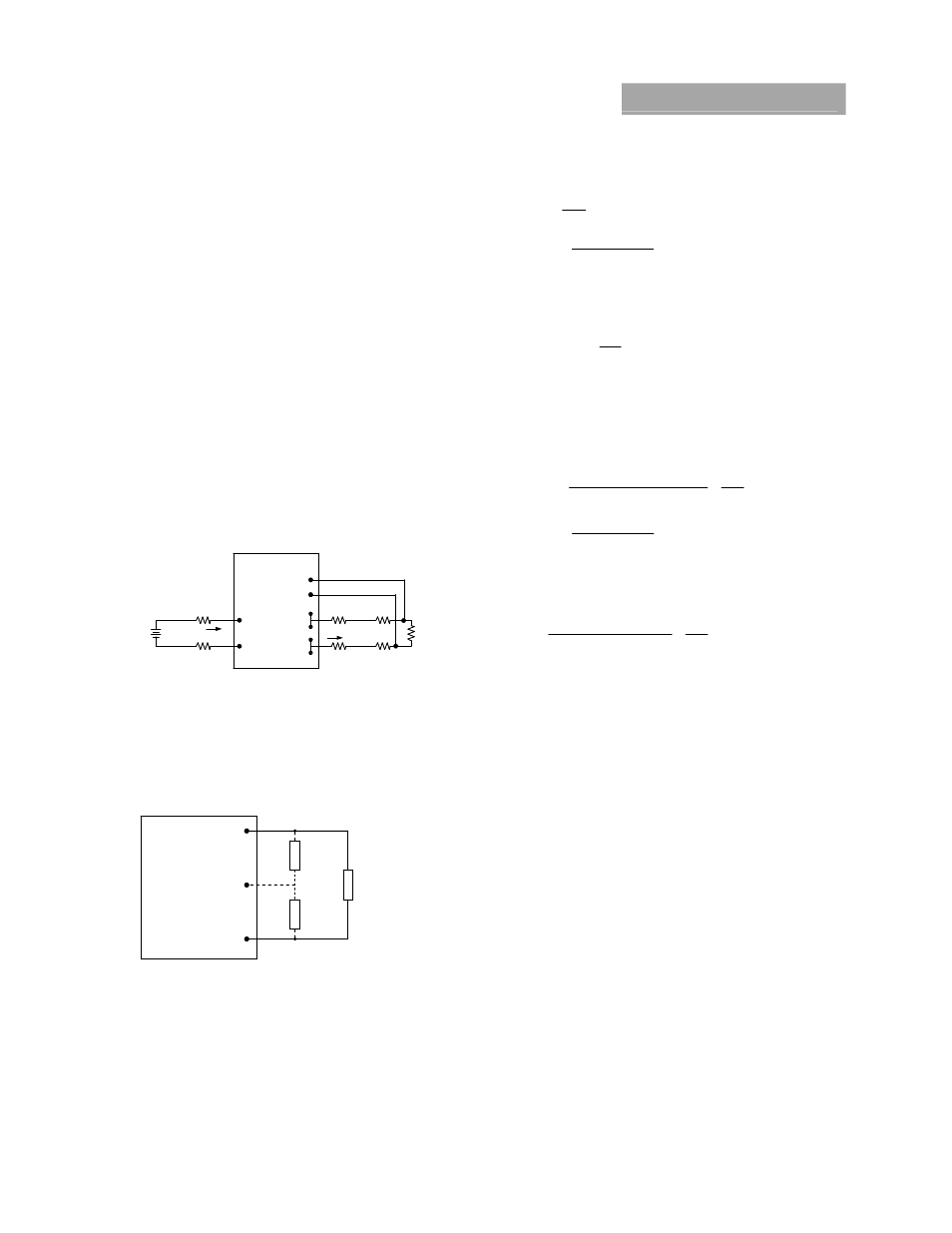
Remote sense minimizes the effects of distribution losses by
regulating the voltage at the remote-sense connections (See
Figure 16). The voltage between the remote-sense pins and the
output terminals must not exceed the output voltage sense
range given in the Feature Specifications table:
[V
O
(+) – V
O
(–)] – [SENSE(+) – SENSE(–)] 0.5 V
Although the output voltage can be increased by both the
remote sense and by the trim, the maximum increase for the
output voltage is not the sum of both. The maximum increase is
the larger of either the remote sense or the trim.
The amount of power delivered by the module is defined as the
voltage at the output terminals multiplied by the output current.
When using remote sense and trim, the output voltage of the
module can be increased, which at the same output current
would increase the power output of the module. Care should be
taken to ensure that the maximum output power of the module
remains at or below the maximum rated power (Maximum
rated power = Vo,set x Io,max).
Figure 16. Circuit Configuration for remote sense.
Trim, Output Voltage Programming
Trimming allows the output voltage set point to be increased or
decreased; this is accomplished by connecting an external
resistor between the TRIM pin and either the V
O
(+) pin or the V
O
(-
) pin.
V
O
(+)
T/C1
V
O
(-)
R
trim-down
LOAD
EBVW020A0B
R
trim-up
Figure 17. Circuit Configuration to Trim Output Voltage.
Connecting an external resistor (R
trim-down
) between the T/C1 pin
and the Vo(-) (or Sense(-)) pin decreases the output voltage set
point. To maintain set point accuracy, the trim resistor
tolerance should be ±1.0%.
The following equation determines the required external
resistor value to obtain a percentage output voltage change of
∆%
22
.
10
%
511
down
trim
R
Where
100
%
,
,
set
o
desired
set
o
V
V
V
For example, to trim-down the output voltage of the module by
20% to 9.6V, Rtrim-down is calculated as follows:
20
%
k
k
R
down
trim
3
.
15
22
.
10
20
511
Connecting an external resistor (R
trim-up
) between the T/C1 pin
and the V
O
(+) (or Sense (+)) pin increases the output voltage set
point. The following equations determine the required external
resistor value to obtain a percentage output voltage change of
∆%:
22
.
10
%
511
%
225
.
1
%)
100
(
11
.
5
, set
o
up
trim
V
R
Where
100
%
,
,
set
o
set
o
desired
V
V
V
For example, to trim-up the output voltage of the module by 5%
to 12.6V, R
trim-up
is calculated is as follows:
5
%
k
k
R
up
trim
8
.
938
22
.
10
5
511
5
225
.
1
)
5
100
(
0
.
12
11
.
5
The voltage between the Vo(+) and Vo(–) terminals must not
exceed the minimum output overvoltage protection value
shown in the Feature Specifications table. This limit includes
any increase in voltage due to remote-sense compensation and
output voltage set-point adjustment trim.
Although the output voltage can be increased by both the
remote sense and by the trim, the maximum increase for the
output voltage is not the sum of both. The maximum increase is
the larger of either the remote sense or the trim. The amount of
power delivered by the module is defined as the voltage at the
output terminals multiplied by the output current. When using
remote sense and trim, the output voltage of the module can be
increased, which at the same output current would increase the
power output of the module. Care should be taken to ensure
that the maximum output power of the module remains at or
below the maximum rated power (Maximum rated power =
V
O,set
x I
O,max
).
Thermal Considerations
The power modules operate in a variety of thermal
environments and sufficient cooling should be provided to help
ensure reliable operation.
Thermal considerations include ambient temperature, airflow,
module power dissipation, and the need for increased reliability.
A reduction in the operating temperature of the module will
result in an increase in reliability.
V
O
(+)
SENSE(+)
SENSE(–)
V
O
(–)
V
I
(+)
V
I
(-)
I
O
LOAD
CONTACT AND
DISTRIBUTION LOSSE
SUPPL
Y
I
I
CONTACT
RESISTANCE