Data sheet, Layout considerations, Through-hole lead-free soldering information – GE Industrial Solutions EBVW020A0B Barracuda Series User Manual
Page 11: Reflow lead-free soldering information
GE
Data Sheet
EBVW020A0B Barracuda Series; DC-DC Converter Power Modules
36-75Vdc Input; 12.0Vdc, 20.0A, 240W Output
July 22, 2013
©2012 General Electric Company. All rights reserved.
Page 11
OUTP
U
T
CURRE
NT, I
O
(A)
LOCAL AMBIENT TEMPERATURE, T
A
(C)
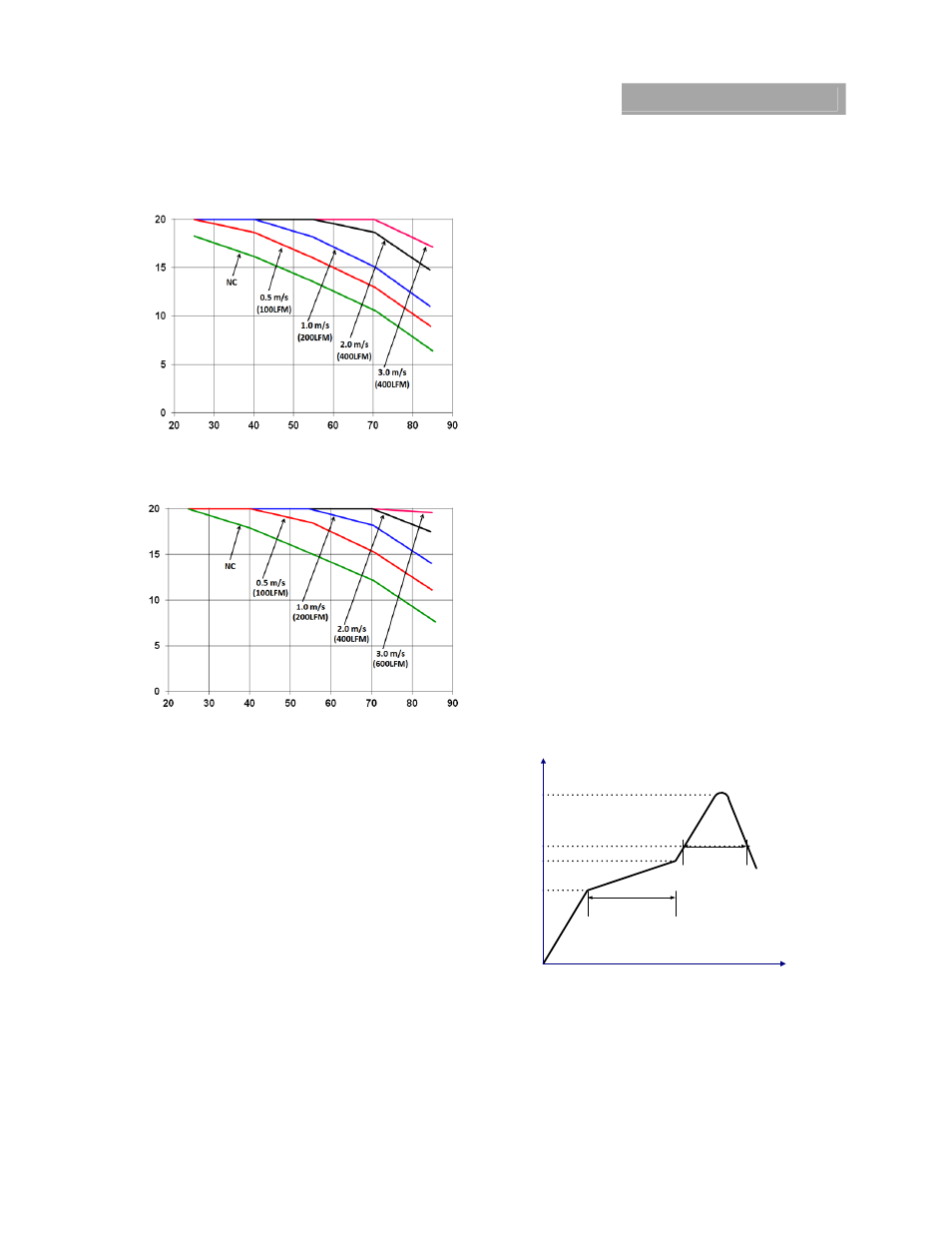
Figure 21. Output Current Derating for the Base Plate
EBVW020A0Bxx-H in the Transverse Orientation; Airflow
Direction from Vin(-) to Vin(+); Vin = 48V.
OUTP
UT CU
RRENT, I
O
(A)
LOCAL AMBIENT TEMPERATURE, T
A
(C)
Figure 22. Output Current Derating for the Base Plate
EBVW020A0Bxx-H and 0.25” heat sink in the Transverse
Orientation; Airflow Direction from Vin(-) to Vin(+); Vin = 48V.
Layout Considerations
The EBVW020 power module series are low profile in order to
be used in fine pitch system card architectures. As such,
component clearance between the bottom of the power
module and the mounting board is limited. Avoid placing
copper areas on the outer layer directly underneath the power
module. Also avoid placing via interconnects underneath the
power module.
For additional layout guide-lines, refer to FLT007A0Z Data
Sheet.
Through-Hole Lead-Free Soldering
Information
The RoHS-compliant, Z version, through-hole products use the
SAC (Sn/Ag/Cu) Pb-free solder and RoHS-compliant
components. The non-Z version products use lead-tin (Pb/Sn)
solder and RoHS-compliant components. Both version modules
are designed to be processed through single or dual wave
soldering machines. The pins have an RoHS-compliant, pure tin
finish that is compatible with both Pb and Pb-free wave
soldering processes. A maximum preheat rate of 3C/s is
suggested. The wave preheat process should be such that the
temperature of the power module board is kept below 210C.
For Pb solder, the recommended pot temperature is 260C,
while the Pb-free solder pot is 270C max. Not all RoHS-
compliant through-hole products can be processed with paste-
through-hole Pb or Pb-free reflow process. If additional
information is needed, please consult with your GE
representative for more details.
Reflow Lead-Free Soldering Information
The RoHS-compliant through-hole products can be processed
with the following paste-through-hole Pb or Pb-free reflow
process.
Max. sustain temperature :
245C (J-STD-020C Table 4-2: Packaging Thickness>=2.5
mm
/
Volume > 2000
mm
3
),
Peak temperature over 245C is not suggested due to the
potential reliability risk of components under continuous high-
temperature.
Min. sustain duration above 217C : 90 seconds
Min. sustain duration above 180C : 150 seconds
Max. heat up rate: 3C/sec
Max. cool down rate: 4C/sec
In compliance with JEDEC J-STD-020C spec for 2 times reflow
requirement.
Pb-free Reflow Profile
BMP module will comply with J-STD-020 Rev. C
(Moisture/Reflow Sensitivity Classification for
Nonhermetic Solid State Surface Mount Devices) for both Pb-
free solder profiles and MSL classification
procedures. BMP will comply with JEDEC J-STD-020C
specification for 3 times reflow requirement. The suggested Pb-
free solder paste is Sn/Ag/Cu (SAC). The recommended linear
reflow profile using Sn/Ag/Cu solder is shown in Figure 23.
Time
T
e
m
p
Ramp up
max. 3
°C/Sec
Ramp down
max. 4
°C/Sec
Time Limited 90 Sec.
above 217°C
Preheat time
100-150 Sec.
Peak Temp. 240 -245
°C
25
°C
150
°C
200
°C
217
°C
Figure 23. Recommended linear reflow profile using
Sn/Ag/Cu solder.
MSL Rating
The EBVW020A0BA modules have a MSL rating of 2a.
Storage and Handling
The recommended storage environment and handling
procedures for moisture-sensitive surface mount packages is