OSRAM OPTOTRONIC Constant current LED power supplies with 3DIM User Manual
Page 44
44
LEDset APPLICATIONS
Using two lookup tables – one for the temperature and one
for the Vset – allows the designer to be very fl exible:
• The NTC can be changed by modifying only the points of
the temperature lookup table.
• The Vset output characteristic can be changed (e.g. when
the temperature monitor system is used for a different lumi-
naire) by modifying only the points of the Vset lookup table.
• By storing more than one lookup table for the temperature
and the Vset (the only limitation is the available memory
size), more applications can be covered by the same MCU
and the same fi rmware. In this case, the correct table con-
fi guration has to be selected by pulling one or more MCU
pins at +5 V or GND.
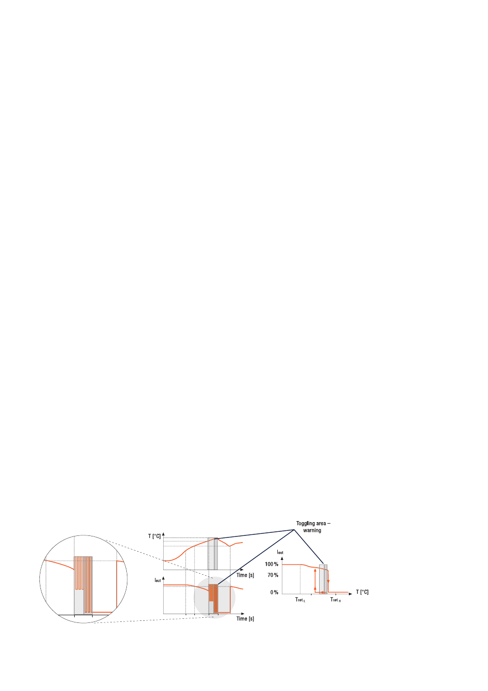
• Since the Vset output is generated digitally by the MCU,
it is possible to toggle it between two values in a certain
temperature range and with a chosen frequency (low
enough to be far from the cut-off frequency of the pass
band of the used ECG), generating a light toggling if nec-
essary. The example below (fi gure 43) shows a possible
implementation. Reaching the determined temperature be-
fore the overtemperature protection value, a toggling be-
tween two current levels (e.g. 100–50 % or 100–0 %) al-
lows the luminaire to warn the user about a possible shut-
down situation.
• A simpler way to signalize the LED module status can be
provided by a small colored LED (e.g. blue LED) connected
to a general-purpose output pin of the MCU. This LED can
be placed directly on the LED module or somewhere else
in the luminaire.
• A UART communication interface (see fi gure 44) realized
by an IR emitter diode and an IR transistor receiver (e.g.
SFH320FA) allows the digital communication of the lumi-
naire status and enables the manufacturer to customize
the luminaire directly at the end of the production line (i.e.
by downloading the lookup tables) or even to upgrade the
luminaire system behavior after installation (see fi gure 45).
Moreover, the IR emitter diode and IR transistor receiver
can be placed directly on the LED module (option 1) or in
a different, more convenient space of the luminaire system
(option 2).
Figure 43: Example of overtemperature warning by LED module toggling.