SENA Parani-BCD110V3 User Manual
Page 37
Sena Technologies, Inc
37
Synchronization Input/Synchronization Output for DIO Synchronization Configuration. The DIO1
of BCD2 is also set as Digital Output for I/O Configuration and Synchronization
Input/Synchronization Output for DIO Synchronization Configuration. When DIO1 status of BCD1
changes, DIO1 status of BCD2 is synchronized as to DIO1 status of BCD1. In same way, DIO1
status of BCD1 is synchronized with DIO1 status of BCD2, too. In case of Output/Output
Synchronization, of two Parani-BCD110V3s connected on I/O profile, when one device changes
in DIO status by AT command, the other device is automatically synchronized.
* Each 5 DIO pin separately works. That means, each DIO pin can be set as Input/Output
Synchronization or Output/Output Synchronization.
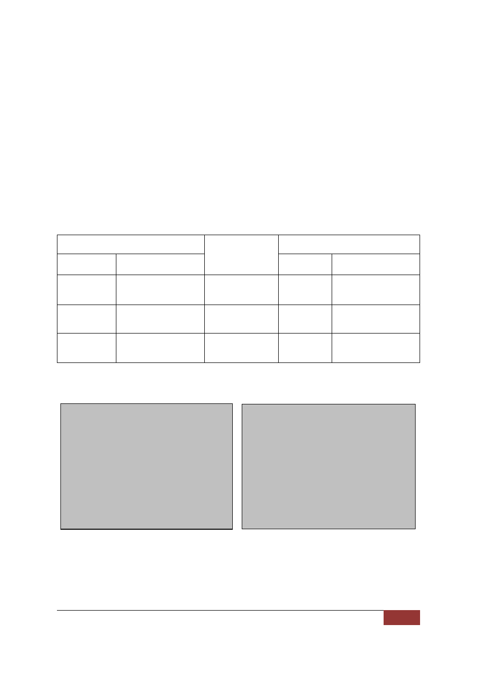
Table 5-4 and Figure 5-3 below describes how both Parani-BCD110V3s of the I/O profile
connection works according to I/O Configuration and DIO Synchronization Configuration.
Table 5-4 Way to synchronize DIO
BCD 1
Way to
Synchronize
BCD 2
I/O
Configuration
DIO Synchronization
Configuration
I/O
Configuration
DIO Synchronization
Configuration
Digital Input
Synchronization Input
Input/Output
synchronization
(BCD 1->BCD 2)
Digital
Output
Synchronization output
Digital Output
Synchronization Output
Input/Output
synchronization
(BCD 1<-BCD 2)
Digital Input
Synchronization Input
Digital Output
Synchronization Input/
Synchronization Output
Output/Output
synchronization
(BCD 1<->BCD2)
Digital
Output
Synchronization Input/
Synchronization Output
Example of DIO Synchronization
BCD 1
at+setio=0011334
OK
at+iosync=11223
OK
atz
OK
at+ioconnect0001951330fe
OK
IOCONNECT 0001951330FE
BCD 2
at+setio=0033114
OK
atz
OK
at+iosync=22113
OK
at+btscan
OK
IOCONNECT 0001951330FD