SENA ProBee-ZE10 User Manual
Page 52
52
ProBee-ZE10 User Guide Rev.1.5
Temperature(℃) ={ Volt(mV) -600(mV)} * 0.1(℃/mV)
Note: The LED On/Off switch (SW20) should be placed to LED_OFF.
6.3.9
Light Sensor
The GPIO_6 of the ZE10 is routed to the light sensor. Approximately, the relationship between illumination
and analog input is as follows:
Illumination(Lux) = Volt(mV) * 0.25(Lux/mV)
Note: The LED On/Off switch (SW20) should be placed to LED_OFF.
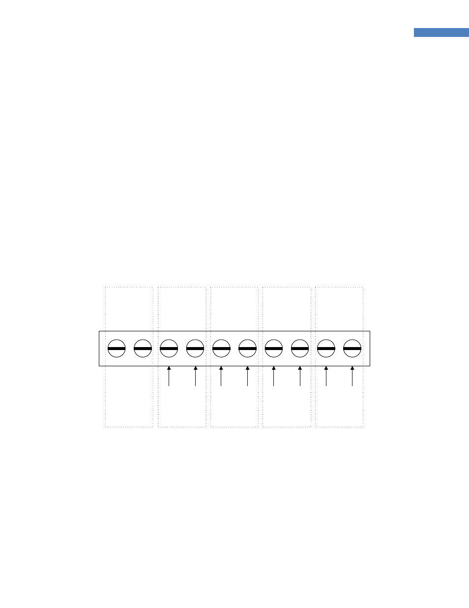
6.3.10 Terminal Block
The development board has a terminal block for external analog inputs. Figure 6-2 shows the layout of
the terminal block. To use external analog inputs instead of the variable resistors, temperature sensor or
light sensor, the ADC_0 (SW4), ADC_1 (SW5), ADC_2 (SW6) or ADC_3 (SW7) should be placed on
EXT_0, EXT_1, EXT_2, or EXT_3.
Reserved
ADC_3
ADC_0
ADC_2
ADC_1
GND
AI0
GND
AI1
GND
AI3
GND
AI2
Figure 6-2 Terminal Block for External Anlalog Inputs
Note: The LED On/Off switch (SW20) should be placed to LED_OFF.
6.4
Configuration Example #1: 1 Coordinator, 1 Router and 1 End-Device
Here is the example configuration to help to start with the ZE10 and the development kit. The goal of this
example is to provide hardware configuration and AT commands for the scenario as below:
One ZE10 module acts as a coordinator and it is connected to a host computer via USB cable.
One ZE10 module acts as a router and it sends temperature sensor, light sensor and digital
inputs to the coordinator every second.