SENA ProBee-ZE10 User Manual
Page 51
51
ProBee-ZE10 User Guide Rev.1.5
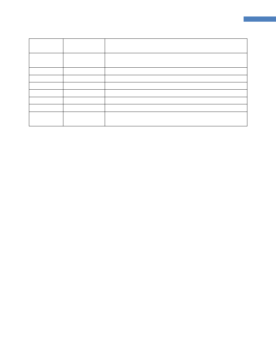
Digital Input with Button Switch (SW15, Active Low or Active High)
Analog Input with Light Sensor (U7)
17
GPIO_12
Digital Output with LED(CR19) Display (Active High)
Digital Input with Button Switch (SW17, Active Low or Active High)
18
GPIO_11
UART DSR Input
19
GPIO_10
UART DTR Output
20
UART_RXD
UART Data Input
21
UART_TXD
UART Data Output
22
GPIO_8
UART CTS Input
23
GPIO_9
UART RTS Output
24
GPIO_7
Digital Output with LED(CR18) Display (Active High)
Digital Input with Button Switch (SW16, Active Low or Active High)
6.3.5
LEDs (CR12-19)
The development board has 8 LEDs for digital output. To enable the LEDs, the GPIO_OUT (SW20) switch
should be set to LED_ON. The LEDs are turned on when the related GPIO pins of the ZE10 are high.
Note: The ADC_0~3 switches (SW4~7) should be placed to EXT_0~3.
6.3.6
Button Switches (SW10-17)
The development board has 8 button switches for digital input. The switches can be configured as active
high or active low with the GPIO_IN (SW19) switch.
Note: The ADC_0~3 switches (SW4~7) should be placed to EXT_0~3.
Note: The LED On/Off switch (SW20) should be placed to LED_OFF.
Note: If the GPIO_IN (SW19) is set to Active High, GPIO pull up/down option should be set to Pull-Down
(ATS41=0). If the GPIO_IN (SW19) is set to Active Low, GPIO pull up/down option should be set to Pull-
Up. (ATS41=1)
6.3.7
Variable Resistors (VR1, VR2)
There are two variable resistors for analog inputs on the development board. The analog inputs can be
read with the GPIO_3 and GPIO_4. To enable the variable resistors, the ADC_0 and ADC_1 switches
should be placed to VR_0 and VR_1.
Note: The LED On/Off switch (SW20) should be placed to LED_OFF.
6.3.8
Temperature Sensor
The GPIO_5 of the ZE10 is routed to the temperature sensor. The relationship between temperature and
analog input is as follows: